Constructing method of cable-stayed bridge and temporary cable therefor

a construction method and cable-stayed technology, applied in the direction of cable-stayed bridges, bridges, machine supports, etc., can solve the problems of increasing the cross section of the segment b>120/b> unnecessarily, requiring a lot of time to construct the entire bridge, and wasting resources and increasing costs. , to achieve the effect of preventing unnecessary expansion of the cross section of the cable, preventing waste of resources, and preventing the expansion

Inactive Publication Date: 2012-08-30
DONG A UNIV RES FOUND FOR IND ACAD COOP
View PDF13 Cites 37 Cited by
  • Summary
  • Abstract
  • Description
  • Claims
  • Application Information

AI Technical Summary

Benefits of technology

[0014]According to the present invention, since the stay cable is pre-installed in the stress-free state without introduction of initial tension, unnecessary expansion of a cross section of the stay cable, which is caused by the introduction of the initial tension, can be prevented, unlike in the related-art cantilever constructing method. Therefore, a waste of resources and an increased material cost can be prevented. Also, since stressing device to introduce the initial tension is not required, a cost can be saved and a construction period can be shortened. Furthermore, since initial tension is not introduced to the stay cable in the present invention, a longitudinal axis force exerted on the segment can be minimized, and as a result, a cross section of the segment can be reduced.
[0015]Also, according to the present invention, since all of the stay cables are installe

Problems solved by technology

However, since the related-art constructing method should perform the steps for installing the segment 120, anchoring the stay cable 120, and introducing the initial tension in sequent, it has a disadvantage of requiring much time to construct the entire bridge.
Therefore, there are problems of a waste of resources and an increased cost.
Also, in the related-art constructing method, a great compressive force is generated on the segment 120 in a longitudinal direction (a bridge-axis direction) due to the initial tension introduced to the

Method used


Image

  • Constructing method of cable-stayed bridge and temporary cable therefor
  • Constructing method of cable-stayed bridge and temporary cable therefor
  • Constructing method of cable-stayed bridge and temporary cable therefor

Examples


Embodiment Construction

Technical Object

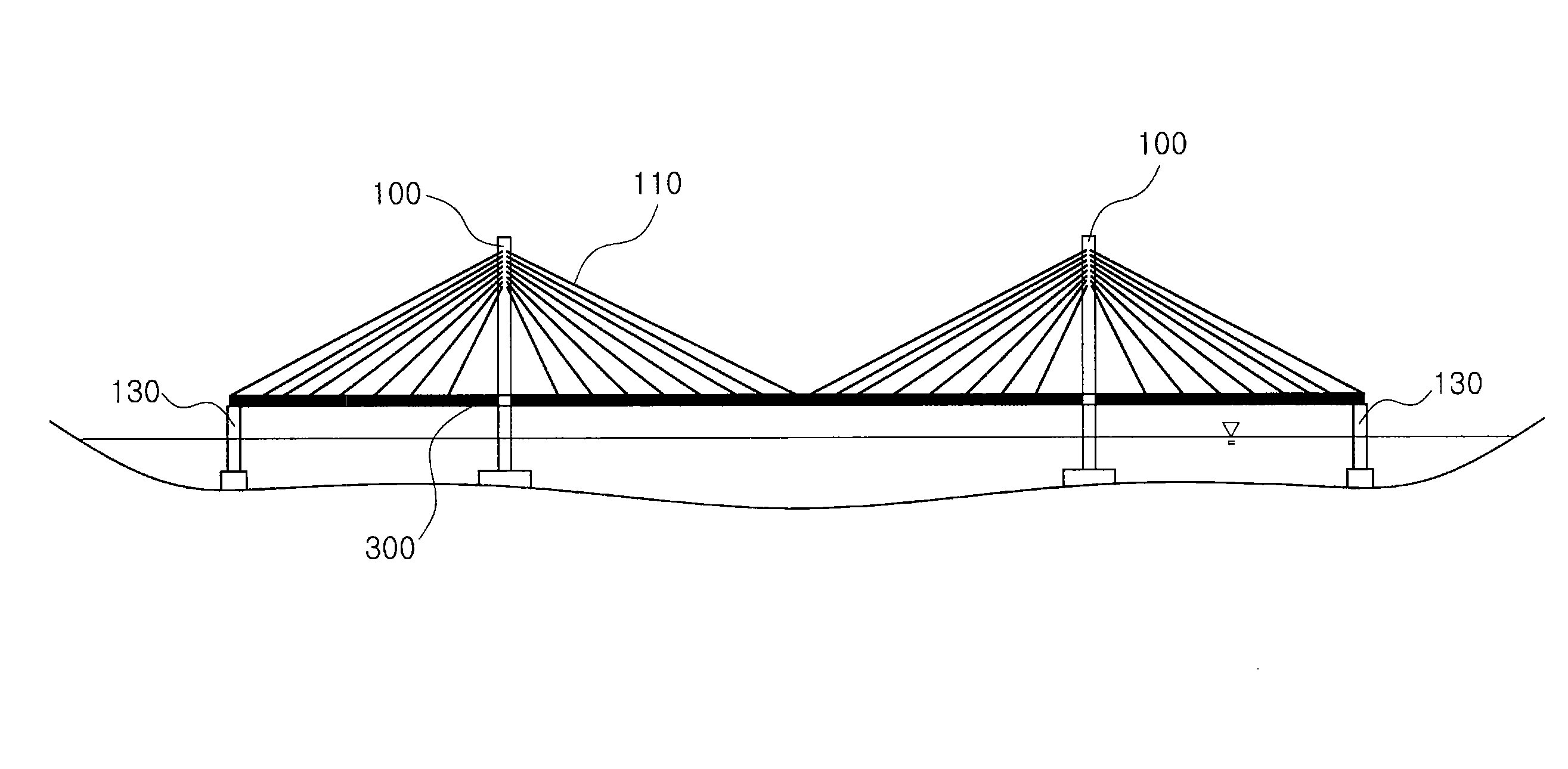
[0008]The present invention has been developed in order to solve the problems and disadvantages of the related-art cable-stayed bridge constructing method using the cantilever method, and an object of the present invention is to minimize a time that is required to install a girder and a stay cable, which require a longest construction period in installing a cable-stayed bridge.

[0009]An object of the present invention is to minimize a stress exerted on a segment of a girder and a stay cable by not introducing initial tension to the stay cable, and accordingly prevent unnecessary expansion of a cross section of the segment and the stay cable and thus prevent a waste of resources and an increased material cost.

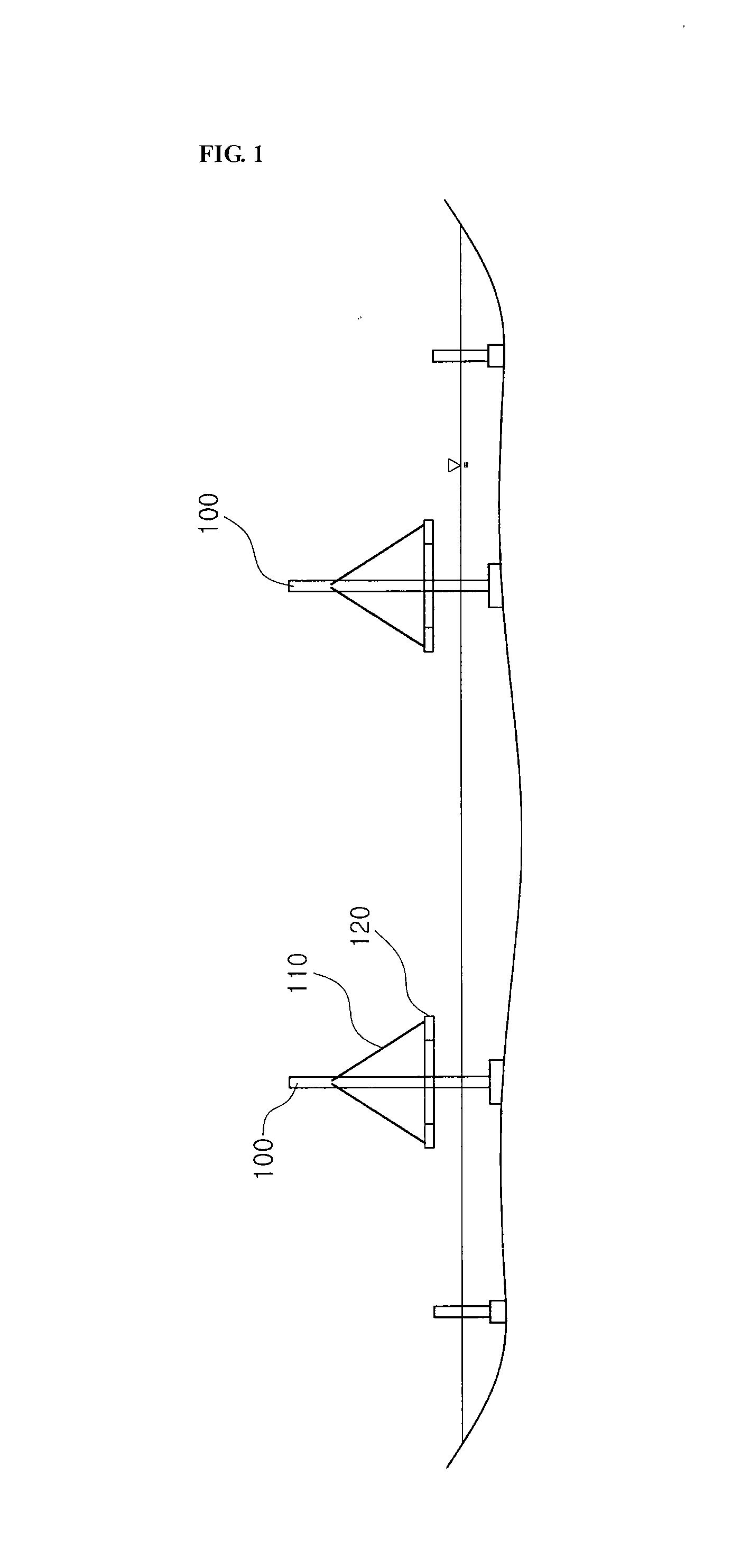
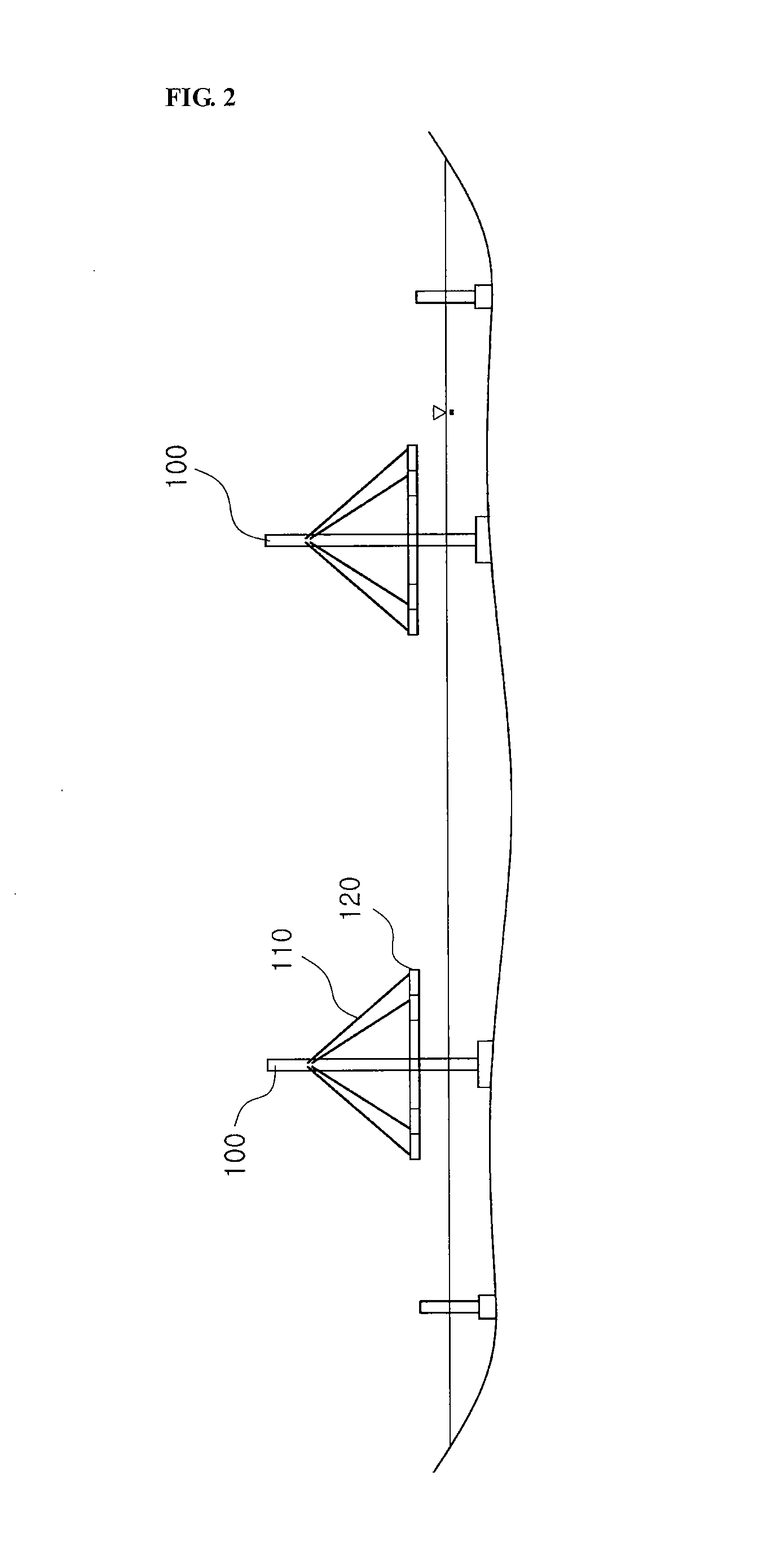
[0010]Also, an object of the present invention is to shorten a construction period required to construct a bridge by using a segment of a big block, minimize use of a connection plate, a high tension bolt, or welding to connect the segments, and minimize the numbe...


PUM


Abstract

The present invention relates to a method for constructing a cable-stayed bridge with a tensionless stay cable, including the steps for: constructing a main tower 100, continuously installing a suspension cable 200 over a main span and a side span, installing a plurality of hangers 210 on the suspension cable 200, arranging an anchorage cable 220 in a longitudinal direction by connecting the anchorage cable 220 to a lower end of the hanger 210, installing a stay cable 110 in sequence, constructing a girder by connecting a segment 300 constituting the girder to each of the stay cables 110 in sequence, and connecting the segments 300 one another in a longitudinal direction, and removing the suspension cable 200, the hanger, and the anchorage cable 220.

Description

TECHNICAL FIELD[0001]The present invention relates to a method for constructing a cable-stayed bridge and a temporary cable therefor. More particularly, the present invention relates to a method for constructing a cable-stayed bridge, which pre-installs a stay cable using a suspension bridge type temporary cable in constructing a cable-stayed bridge, which supports a girder for the upper structure of a bridge, so that a load exerted on the girder and the stay cable, which constitutes an upper structure of the bridge, can be minimized without introduction of initial tension to the stay cable, and a temporary cable therefor.BACKGROUND ART[0002]Advantages of a cable-stayed bridge, which includes a main tower, a stay cable, and a girder as main components, are that it has good appearance and the stay cable serves as an elastic support for the girder and thus transmits a load of the girder to the main tower. Therefore, a bridge having a long span of 200 m or more as a length between main...

Claims


Application Information

Patent Timeline
IPC IPC(8): E01D21/00E01D19/16E01D11/04
CPCE01D21/00E01D11/04
Inventor BYUN, JONG KWANKANG, WON HO
Owner DONG A UNIV RES FOUND FOR IND ACAD COOP
Why Eureka
Try Eureka