System and Method for Stress Field Based Wellbore Steering

a wellbore and stress field technology, applied in the direction of borehole/well accessories, directional drilling, survey, etc., can solve the problems of repeated trial and error learning process, inability to achieve the success of one field, and inability to achieve the success of another field

Active Publication Date: 2012-08-30
BAKER HUGHES HLDG LLC
View PDF1 Cites 22 Cited by
  • Summary
  • Abstract
  • Description
  • Claims
  • Application Information

AI Technical Summary

Problems solved by technology

Successful practices were defined by trial and (sometimes costly and spectacular) error.
However, techniques that were successful in one field were not necessarily successful in other fields, and therefore the trial and error learning process often had to be repeated.
As wells have become more expensive and complex, both in terms of well geometry (reach and length) and access to deep, high temperature, high pore pressure, and high stress regimes, it has become clear that the economic success of field developments can only be assured if geology and tectonics are understood and field activities are designed with that understanding.
Furthermore, constraints on engineering practice based on environmental and societal requirements necessitate specially designed mud formulations and drilling techniques.
Human activities, such as mining and fluid extraction or injection, can also cause local stress changes.
In general, vertical wells are found to be progressively less stable as the regime changes from normal to strike-slip to reverse, and consequently require higher mud weights to drill.
The orientation of the well with respect to the stresses can also affect the cost of the installed hardware necessary to achieve well objectives.
Therefore, wells that are drilled parallel to the least principal stress (SHmin), when stimulated using hydraulic fracturing, will have fractures that are perpendicular to the well axis.
In a cased and perforated well, selectively perforating at discrete intervals and selectively stimulating each interval separately will result in a series of parallel fractures extending radially away from the well.
Wells drilled in orientations that deviate only a small amount from these optimal orientations will be much more difficult to stimulate, and will have geometries of the induced fractures that are significantly different from the desired geometries.

Method used


Image

  • System and Method for Stress Field Based Wellbore Steering
  • System and Method for Stress Field Based Wellbore Steering
  • System and Method for Stress Field Based Wellbore Steering

Examples


Embodiment Construction

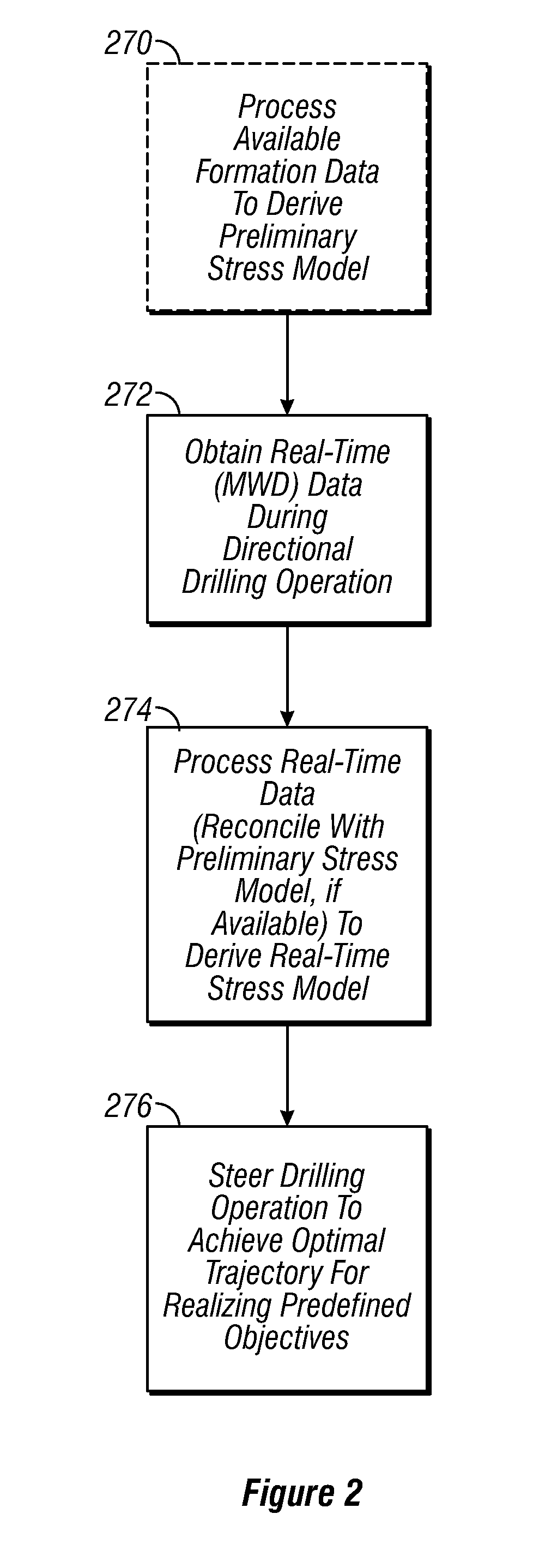
[0040]Referring to FIG. 2, there is shown a flow diagram illustrating geomechanical wellbore steering in accordance with one embodiment of the disclosure. As shown in FIG. 2, formation data for a region into which a borehole is to be drilled may be obtained and processed 270, to derive a preliminary stress model for the region. In an alternate embodiment of the disclosure, information about the stress field may be obtained during drilling operations as discussed below.

[0041]In some cases, prior drilling activity in the region may have occurred such that certain a priori data may be available from which the stress field in the region may be modeled, at least preliminarily. Alternatively, or in addition, one or more offset or pilot boreholes may be drilled in the region to obtain either by measuring while drilling (MWD) and / or by post-drilling measurements using selected instruments, of which there are examples too numerous to itemize herein, providing data from which stress condition...


PUM


Abstract

A system, method and computer-readable medium for developing an earth formation is disclosed. A tool conveyed in a borehole induces a stress in the earth formation proximate a borehole. A sensor assembly obtains a measurement of a physical property of the borehole at a plurality of azimuthal locations in the borehole. The values of the physical property are indicative of the induced stress in the formation. A processor forms an image of the borehole using the obtained measurements of the physical property, estimates an azimuthal variation with borehole depth of the induced stress in the formation from the formed image, and alters an operational parameter of a device for developing the earth formation using the estimated azimuthal variation with depth of the induced stress in the formation.

Description

CROSS-REFERENCES TO RELATED APPLICATIONS[0001]This application is a continuation-in-part of U.S. application Ser. No. 12 / 185,676 filed on Aug. 4, 2008, which claims priority from U.S. Provisional Patent Application Ser. No. 60 / 963,701 filed on Aug. 6, 2007, and which is a continuation-in-part of U.S. patent application Ser. No. 11 / 863,052, filed on Sep. 27, 2007, now issued U.S. Pat. No. 7,548,817, which claimed priority from U.S. Provisional Patent Application Ser. No. 60 / 847,948 filed on Sep. 28, 2006 and from U.S. Provisional Patent Application Ser. No. 60 / 849,962 filed on Oct. 6, 2006.FIELD OF THE DISCLOSURE[0002]The present disclosure relates generally to hydrocarbon exploration and production, and more particularly relates to a method and system for guiding the trajectory of a wellbore.BACKGROUND OF THE DISCLOSURE[0003]In the early years of oil drilling and production, wells were primarily drilled on land, to moderate depths, and with relatively minor horizontal offsets. An em...

Claims


Application Information

Patent Timeline
Patent Type & Authority Applications(United States)
IPC IPC(8): E21B43/16E21B7/04E21B47/00
CPCE21B7/06E21B47/08G01V2210/66G01V1/50G01V11/002E21B49/006
Inventor MOOS, DANIELHASSAN, GAMAL A.GEORGI, DANIEL T.CASTILLO, DAVID A.FABIAN, JOHN
Owner BAKER HUGHES HLDG LLC
Why Eureka
Try Eureka