Bonding of parts with dissimilar thermal expansion coefficients

a technology of thermal expansion coefficient and dissimilarity, applied in the direction of transportation and packaging, basic electric elements, thin material handling, etc., can solve the problems of material breakage, severe restrictions on material selection, and may not be acceptable, functional or economic perspective, and achieve the desired level of relative position accuracy, long-lasting bonding of materials, and high stiffness

Inactive Publication Date: 2005-05-24
AGITYNE CORP
View PDF36 Cites 23 Cited by
  • Summary
  • Abstract
  • Description
  • Claims
  • Application Information

AI Technical Summary

Benefits of technology

[0009]The objective of the invention is to allow long lasting bonding of materials with different thermal expansion coefficients while overcoming the aforementioned problems of the current methods. This is accomplished through the incorporation of an intermediate layer, which has gradual changes in the thermal expansion from one side of the layer to the other. Each side of the layer has a thermal expansion coefficient that is not substantially different from the thermal expansion coefficient of the material with which that side is bonded to. The intermediate layer has a sufficient thickness to avoid fractures or permanent deformation anywhere within the layer and a sufficiently high stiffness to maintain a desired level of accuracy in the relative position of the two materials even after a large number of thermal cycles.
[0010]The key benefit of this method is that the thermally induced strain is distributed across a layer of material rather than being concentrated at the interface. In this way the stress at any given point is reduced, and the material remains in the elastic region so cracks are avoided, thereby creating the basis for a long-term durable bond. In particular, bonding of components that cannot be allowed to migrate over time will benefit from this invention where conventional methods fail in providing a simple and cost effective solution.

Problems solved by technology

In the cases where the two materials have dissimilar thermal expansion coefficients temperature fluctuations may induce fractures or permanent deformation that either cause the two different materials to break apart or shift in position relative to each other.
This approach, however, imposes severe restrictions on the selection of materials and that may not be acceptable from a functional or economic perspective, and, in particular, it excludes the bonding of two different materials with dissimilar thermal expansion coefficients.2. Performing the bonding at the lowest possible temperature to avoid residual forces locked in during cooling following the bonding process.
This approach, however, can often not be utilized due to undesired properties of the low temperature bonding methods and because it still does not address the problems caused during subsequent thermal cycles.3. Minimizing the bonding area between the two materials.
This approach, however, will not function in cases where the overall requirements to the strength of the bond are high or where high positional accuracy of the parts is required.4. The use of a compliant layer that can absorb the thermal mismatch.
This approach, however, will often allow the relative position of the parts being bonded to shift gradually over an extended number of thermal cycles thus jeopardizing product functionality.
This approach, however, will often be costly to fabricate as each layer is deposited as a separate process step, and furthermore it can be a challenge to avoid the use of materials incompatible with the usage of the product.6. The use of a mechanical design that allows relative motion between the parts being joined.
This approach, however, will for many applications allow for too large a relative motion between the parts being joined.

Method used


Image

  • Bonding of parts with dissimilar thermal expansion coefficients
  • Bonding of parts with dissimilar thermal expansion coefficients

Examples


Embodiment Construction

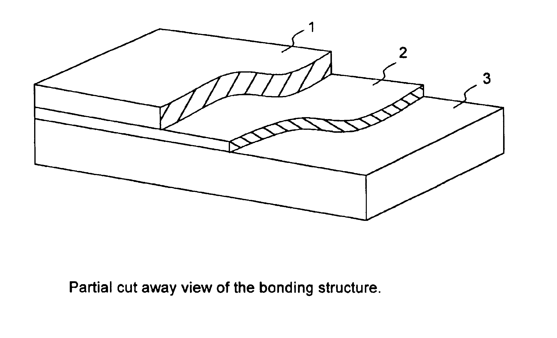
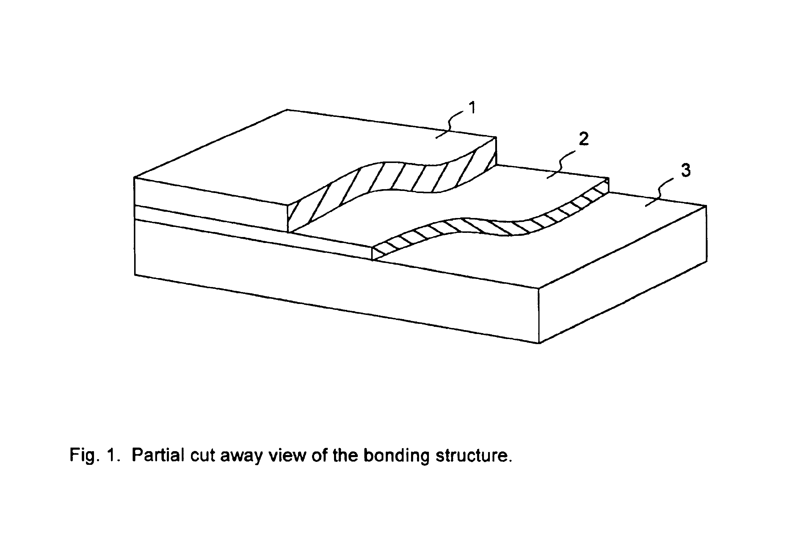
[0012]Some of the preferred embodiments of the present invention are described here. The process will start by identifying the two (or more) materials to be bonded together (1 and 3); these materials can be of any kind, but would generally be solids belong to one of these groups: glasses, pure metals, alloys, semiconductor materials, ceramics, cermets, composites, inorganic polymers or organic polymers. A specific example could be a silicon die that is to be bonded to a sheet formed out of a specific alloy. Additional parameters that must be identified are the temperature range to which the bond will be exposed to, including the lock-in temperature during the bonding process, the coefficients of thermal expansion for the two (or more) materials in this temperature range and the desired physical characteristics of the system.

[0013]The second step is to identify the type of intermediary layer 2, that will be used between the two materials 1 and 3, that are being bonded. The selection ...


PUM

PropertyMeasurementUnit
chemical compositionaaaaaaaaaa
thermal expansion coefficientsaaaaaaaaaa
temperatureaaaaaaaaaa

Abstract

A method for bonding materials with different thermal expansion coefficients is provided. An intermediary layer of glass, ceramics, polymers, metals or composites is inserted between the materials to be bonded; this intermediary layer has a compositional gradient that could have been formed through diffusion processes. The coefficient of thermal expansion changes across the intermediary layer and on each side it is not substantially different from the coefficient of thermal expansion of the material that the layer is facing. In that manner there is nowhere within the intermediate layer or on the interfaces to the materials being bonded that thermally induced stress will cause fractures or significant permanent plastic deformation. The thickness of the intermediary layer depends on the difference in the coefficient of thermal expansion between the two materials being bonded, the temperature range the bond will be exposed to and the elasticity.

Description

CROSS-REFERENCE TO PROVISIONAL PATENT APPLICATION[0001]This patent application is based on the provisional patent “Materials for bonding parts with dissimilar thermal expansion coefficients” filed Mar. 5, 2001 with the No. 60 / 273,070. This provisional patent was filed by Rensselaer Polytechnic Institute (RPI). Feb. 22, 2002 RPI assigned all the rights, title and interest to the intellectual property rights pertaining to this invention to the inventor, Kaspar Tobias Winther. Please see copy of the letter from RPI.BACKGROUND OF THE INVENTION[0002]Permanent bonding between dissimilar materials is required in many products and components. Particularly stringent requirements are found in the manufacture of Microsystems technology based components and products. In the cases where the two materials have dissimilar thermal expansion coefficients temperature fluctuations may induce fractures or permanent deformation that either cause the two different materials to break apart or shift in pos...

Claims


Application Information

Patent Timeline
Patent Type & Authority Patents(United States)
IPC IPC(8): H01L21/762H01L21/02H01L21/20H01L21/70
CPCH01L21/2007H01L21/76251Y10T428/12021
Inventor WINTHER, KASPAR TOBIAS
Owner AGITYNE CORP
Why Eureka
Try Eureka