
Methods, devices systems for extraction of thermal energy from a heat conducting metal conduit

A pipeline, thermal energy technology, applied in pipeline heating/cooling, household refrigeration devices, control/regulation systems, etc., to solve problems such as broken or damaged pipelines

Inactive Publication Date: 2013-08-07
BIOFILM IP
View PDF110 Cites 22 Cited by
  • Summary
  • Abstract
  • Description
  • Claims
  • Application Information

AI Technical Summary

Problems solved by technology

Disadvantages of these and other known intervention systems include the time and cost associated with known intervention techniques, especially involving intervention in subsea wells, and possible breakage or damage to the pipeline due to misalignment of plug placement

Method used


Image

  • Methods, devices systems for extraction of thermal energy from a heat conducting metal conduit
  • Methods, devices systems for extraction of thermal energy from a heat conducting metal conduit
  • Methods, devices systems for extraction of thermal energy from a heat conducting metal conduit

Examples


Embodiment 1

[0363] vertical pipe

[0364] Fabricate and test the CryoPlug cryothermal valve system on a vertical pipeline. exist Figure 13 An exemplary embodiment is schematically illustrated in . The vertical pipeline configuration of Example 1, described in more detail below, contained floating oil through the system at a flow rate of about 550 barrels per day or 10 feet per second (fps).

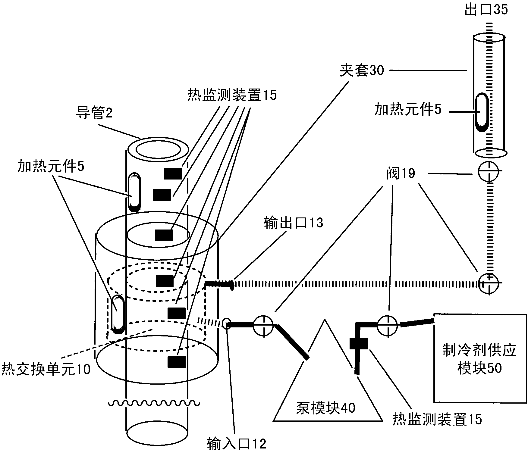
[0365] In this vertical piping system, the system includes a heat exchange unit 10 and a refrigerant injector 67 . In this embodiment, the heat exchange unit 10 includes piping 2 comprising 3 feet carbon steel finned tubes (carbon steel finned tubing, 5 / 8 inch fin height, 1 / 4" fin spacing), 6" section 1a of non-finned carbon steel piping at the top of the finned piping 顶 , and a 6-inch section 1a of non-finned carbon steel piping at the bottom end of the finned piping 底 , to obtain a pipe with a total length of 4 feet. The pipe 2 and each pipe 1a 顶 and 1a 底 A part of it is packed into a ste...

Embodiment 2

[0375] horizontal pipe

[0376] The CryoPlug cryothermal valve system was fabricated and tested on horizontal piping. exist Figure 14A and 14B An exemplary embodiment is schematically illustrated in .

[0377] In this horizontally oriented piping system, the system includes a heat exchange unit 10 and a refrigerant injector 60, an enlarged view of which is shown in Figure 14A shown. In this embodiment, the heat exchange unit 10 includes tubing 2 comprising 6 feet of 304 stainless steel finned tube 2f (stainless steel finned tubing, 3 / 4 inch fin height, 1 / 4 inch fin spacing), and a 12 inch non-finned stainless steel piping section 2a at the left end of the finned piping 2f 左 , and the 12-inch non-finned stainless steel piping section 2a at the right end 右 , to obtain a pipe with a total length of 8 feet. Finned tube 2f and each tube 2a 左 and 2a 右 A part of it is packed into a carbon steel pipe 2c with a diameter of 5 inches as a jacket. 1 / 8 inch steel plate 3 with o...


PUM


Abstract

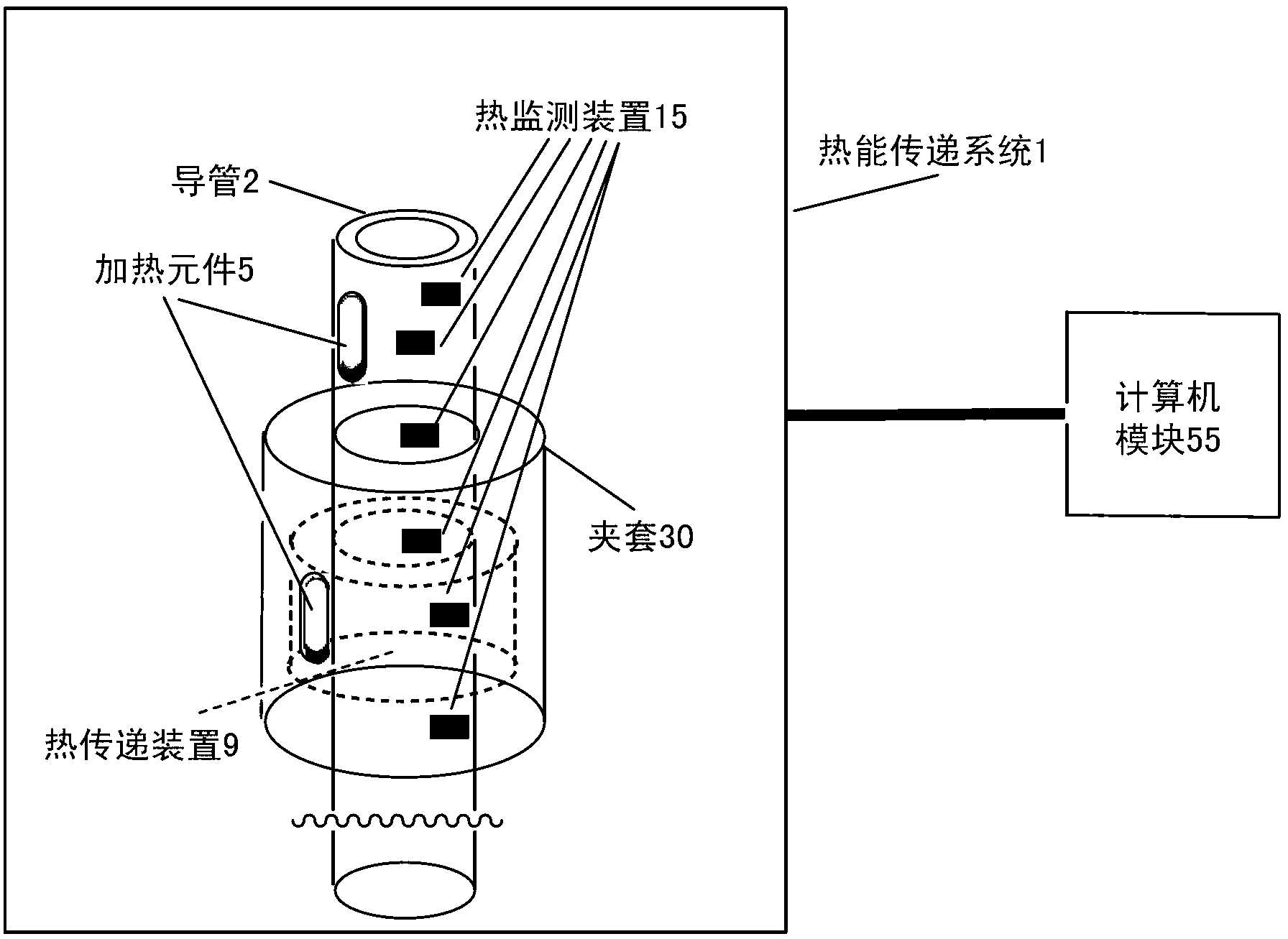
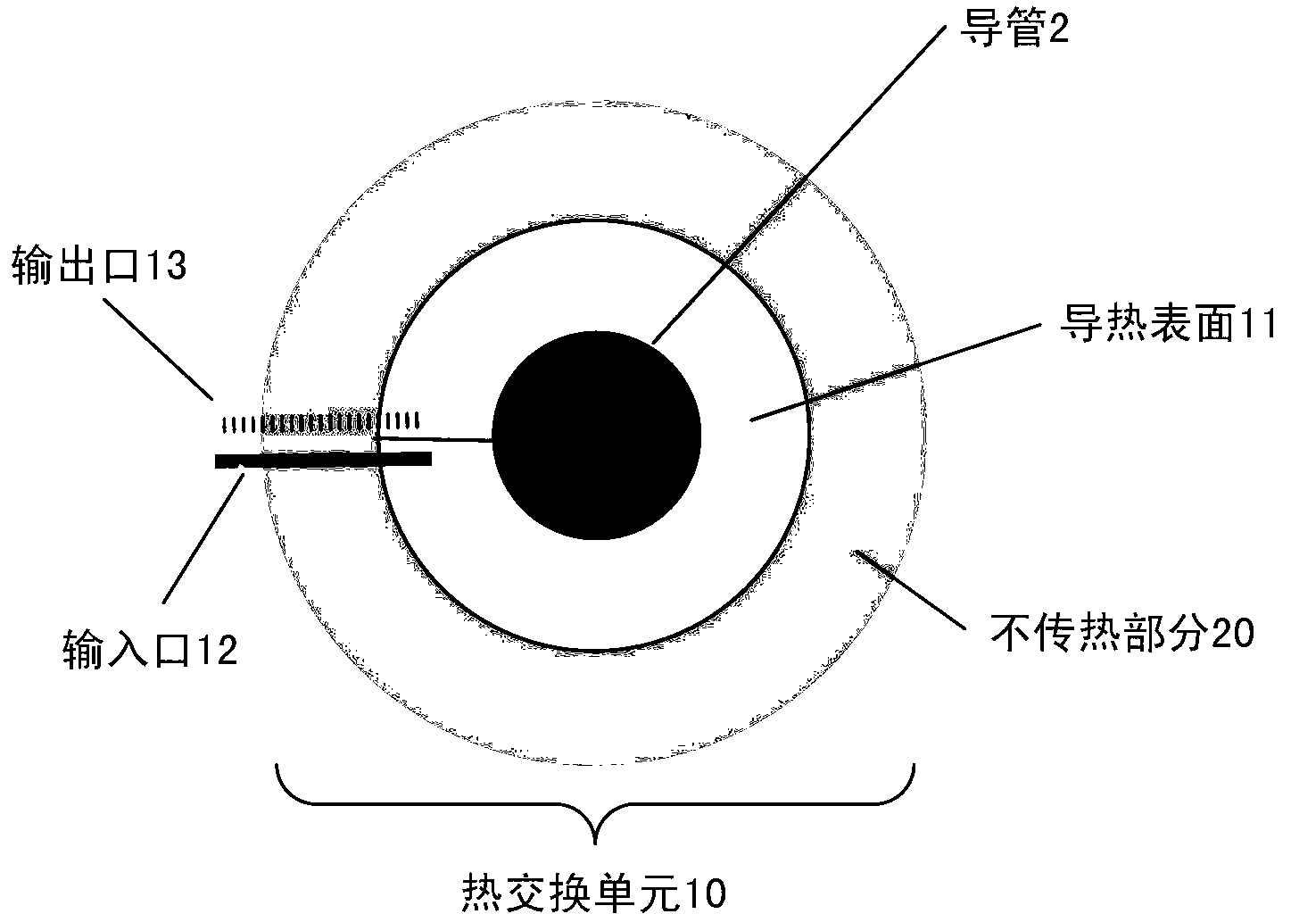
Provided are methods, devices and systems for controlled removal of thermal energy from a fluid within a thermally conducting metal conduit. The system allows for the in situ formation of a reversible plug that can stop the flow of fluid through the conduit, particularly without inducing thermally induced stress fractures or breaches in the conduit. The devices and systems include a thermal transfer device that can be adapted to be in thermal communication with a thermal conducting metal conduit containing a fluid, particularly a flowing fluid. The devices and systems allows for controlled re-heating of the conduit without inducing thermally induced stress fractures or breaches in the conduit to restore fluid flow through the conduit.

Description

[0001] Related Patent Applications [0002] This application claims the benefit of priority of the following patent application: Daniel X. Wray, Robert J. Wray and Henry Cutbirth, filed April 12, 2011, entitled "METHODS, DEVICES AND SYSTEMS FOR EXTRACTION OF THERMAL ENERGY FROM A HEAT CONDUCTING METAL CONDUIT" U.S. Provisional Patent Application 61 / 517,070; Daniel X. Wray and Robert J. Wray, filed July 16, 2010, entitled "METHODS, DEVICES AND SYSTEMS FOR EXTRACTION OFTHERMAL ENERGY FROM A HEAT CONDUCTING METALCONDUIT" Patent Application 61 / 399,746, and U.S. Provisional Patent Application 61 / 397,759, entitled "METHODS, DEVICES AND SYSTEMS FOREXTRACTION OF THERMAL ENERGY FROM A HEAT CONDUCTING METAL CONDUIT," filed June 15, 2010 by Daniel X. Wray. [0003] This application is also related to corresponding U.S. Patent Application 13 / 161,411, entitled "METHODS, DEVICESAND SYSTEMS FOR EXTRACTION OF THERMAL ENERGY FROM AHEAT CONDUCTING METAL CONDUIT," filed on the same date as this ap...

Claims


Application Information

Patent Timeline
Patent Type & Authority Applications(China)
IPC IPC(8): F16L55/103G05D23/19
CPCG05D23/192F16L55/103F28D7/10F16L53/00F16L55/164F25B21/02F25D3/10F25D15/00F25B2321/002Y10T137/0391Y02E10/10F28F13/06
Inventor D·X·雷伊R·J·雷伊H·卡特比尔特
Owner BIOFILM IP
Learn More