Wireless Energy Transfer Using Arrays of Resonant Objects

a technology of resonant objects and wireless energy, applied in the direction of electric vehicles, charging stations, transportation and packaging, etc., can solve the problems of ineffective inductive coupling methods, inefficient resonant coupling, and inability to achieve resonant coupling when the distance is greater, so as to facilitate energy transfer and extend the range of efficient wireless energy transfer

Inactive Publication Date: 2012-08-30
MITSUBISHI ELECTRIC RES LAB INC
View PDF10 Cites 18 Cited by
  • Summary
  • Abstract
  • Description
  • Claims
  • Application Information

AI Technical Summary

Benefits of technology

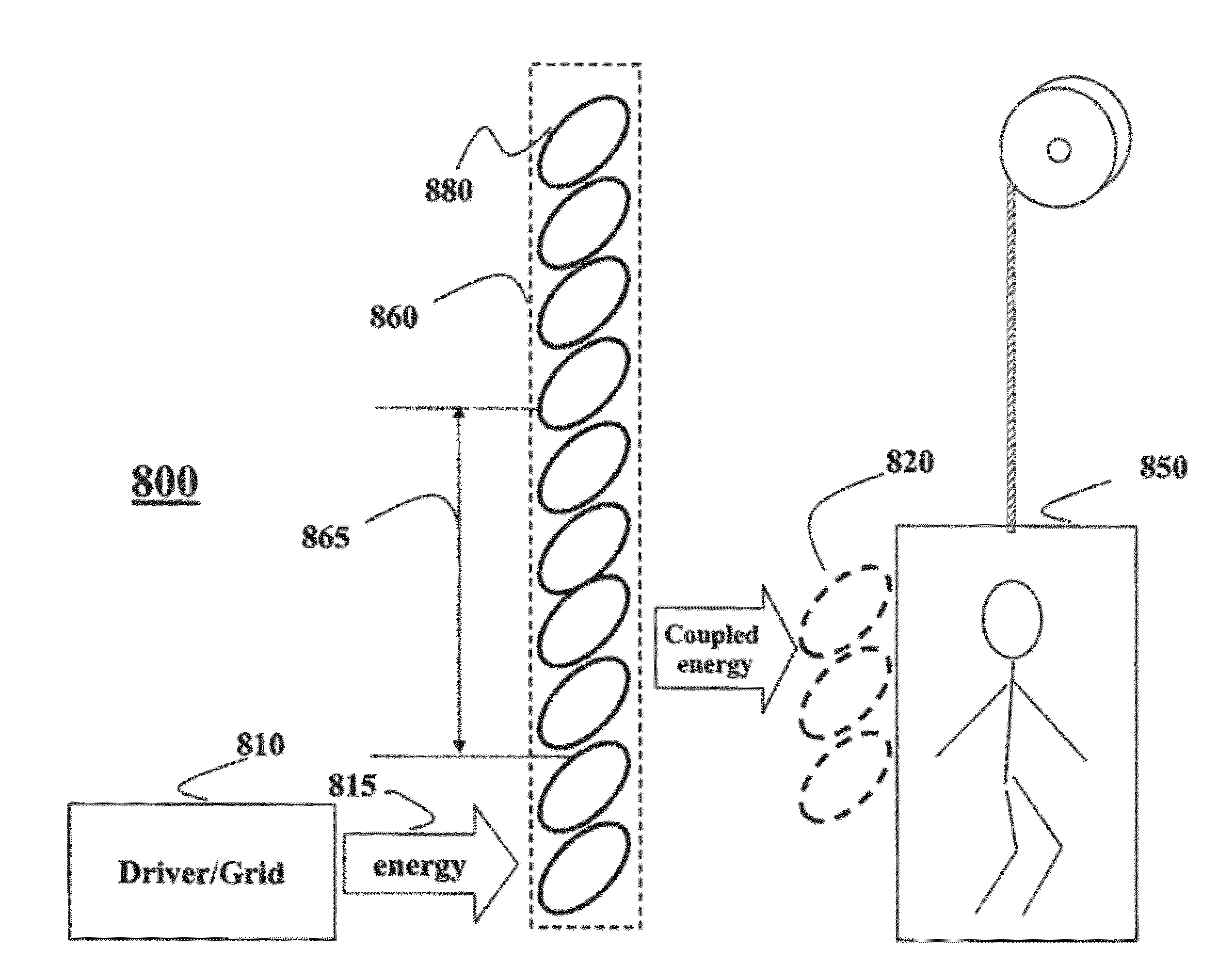
[0013]The embodiments of the invention use an array of strongly coupled resonant objects to extend a ran

Problems solved by technology

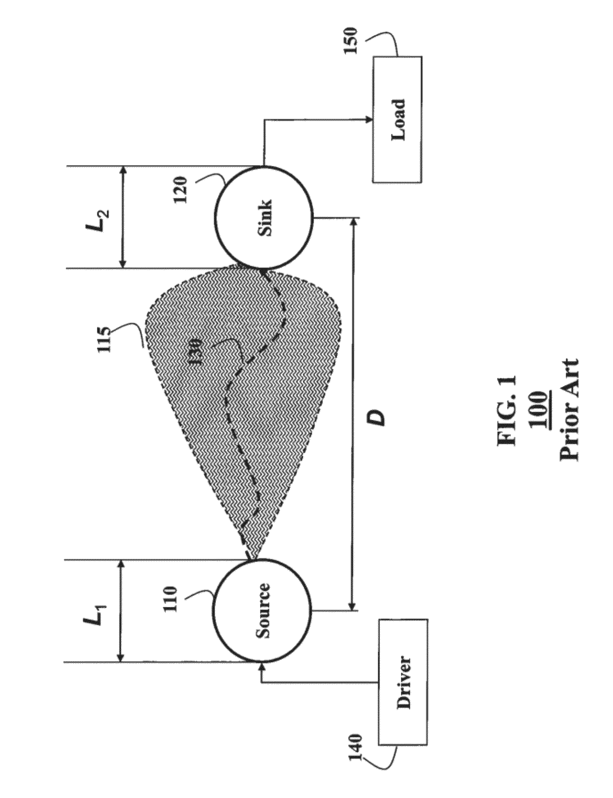
To optimize the energy, a distance between the source and the sink should be as small as possible, because over greater distances the inductive coupling method is ineffective.
However, the re

Method used


Image

  • Wireless Energy Transfer Using Arrays of Resonant Objects
  • Wireless Energy Transfer Using Arrays of Resonant Objects
  • Wireless Energy Transfer Using Arrays of Resonant Objects

Examples


example

[0081

[0082]FIG. 9 shows another example embodiment. Spiral resonators 910 resonating at 27 MHz form the resonator arrays of the energy source 920 and the energy sink 930. For example, both resonator arrays have 6 spiral elements. Two loop antennas with R radius are used as the energy driver 940 and the load 950.

[0083]The separation between driver / load and source array / sink array is D2. The distance between the energy source and sink array is D.

[0084]For example, the energy is provided to the driver via wired cable and then provided to the source via, e.g., inductive coupling at resonant frequency. The specified resonant mode is excited in the system and the energy redistributed over the whole system according to the resonant mode. The load 950 extracts the energy wireless out of the system from the energy sink 930. When the energy is extracted from the system, energy balance of the system is disturbed and more energy is provided from the driver to maintain the balance. Accordingly, ...


PUM


Abstract

A system for exchanging energy wirelessly includes an array of at least three objects, wherein the objects have similar resonant frequencies, wherein each object is electromagnetic (EM) and non-radiative and generates an EM near-field in response to receiving the energy. Each object is electrically isolated from the other objects and arranged at a distance from all other objects, such that upon receiving the energy, the object is strongly coupled to at least one other object via a resonant coupling of evanescent waves. An energy driver provides the energy at the resonant frequency to at least one object in the array, such that, during an operation of the system, the energy is distributed from the at least one object to all other objects in the array via the resonant coupling of the evanescent waves.

Description

RELATED APPLICATIONS[0001]The present invention claims priority to U.S. Provisional Patent Application 61 / 447599, “Wireless Energy Transfer Using Array of Resonant Objects,” filed by Wang et al. on Feb. 28, 2011, and is related to U.S. Patent Applications (MERL-2421), “Tuning electromagnetic fields characteristics for wireless energy transfer using arrays of resonant objects,” co-filed herewith by Wang et al. on ______, 2011, and U.S. Patent Application (MERL-2429) “System and method for automatically optimizing wireless power, co-filed by Yerazunis et al, on ______, 2011, all incorporated herein by reference.FIELD OF THE INVENTION[0002]This invention relates generally to transferring energy wirelessly, and more particularly to transferring energy using an array of resonant objects.BACKGROUND OF THE INVENTION[0003]Wireless Energy Transfer[0004]Inductive coupling is used in a number of wireless energy transfer systems, such as a cordless electronic toothbrush, or vehicle batteries. I...

Claims


Application Information

Patent Timeline
IPC IPC(8): H02J17/00
CPCH02J5/005H02J17/00H04B5/0087H04B5/0081H04B5/0037Y02T10/7072Y04S30/14B66B7/00B60L53/65H02J50/12Y02T90/12Y02T90/167Y02T10/70H02J50/05H02J50/40H02J50/10H02J50/70Y02T90/14Y02T90/16H02J50/20
Inventor WANG, BINGNANTEO, KOON HOOYERAZUNIS, WILLIAM S.ZHANG, JINYUN
Owner MITSUBISHI ELECTRIC RES LAB INC
Why Eureka
Try Eureka