Eureka AIR delivers breakthrough ideas for toughest innovation challenges, trusted by R&D personnel around the world.

Insulating support flange for current loop system

Active Publication Date: 2012-08-30
ROCKWELL AUTOMATION TECH
View PDF6 Cites 0 Cited by
  • Summary
  • Abstract
  • Description
  • Claims
  • Application Information

AI Technical Summary

Benefits of technology

[0007]The present invention relates generally to systems and methods for isolating a current loop conductor of a current loop system of a pre-charge circuit from a plurality of current transformers disposed around the current loop conductor. In particular, the embodiments described herein include an insulating support flange having a first tubular section, a second tubular section radially disposed around the first tubular section and connected to the first tubular section via a solid annular section extending radially outward from the first tubular section to a first end of the second tubular section, an annular base extending radially outward from a second end of the second tubular section, and a plurality of prongs extending axially from or near to an outer circumference of the annular base, wherein each of the prongs comprises an end face that is angled toward the second tubular section. The insulating support flanges are configured to mate with each other along an axial direction of the current loop conductor. In addition, each of the plurality of current transformers is installed (i.e., held in place) between the prongs, annular base, and second annular section of its respective insulating support flange. As such, a fixed open air space between the first and second annular sections of the insulating support flanges isolates the current transformers from the current loop conductor, thereby reducing the possibility of discharge between the current transformers and the current loop conductor.

Problems solved by technology

As such, a fixed open air space between the first and second annular sections of the insulating support flanges isolates the current transformers from the current loop conductor, thereby reducing the possibility of discharge between the current transformers and the current loop conductor.

Method used


Image

  • Insulating support flange for current loop system
  • Insulating support flange for current loop system
  • Insulating support flange for current loop system

Examples


Embodiment Construction

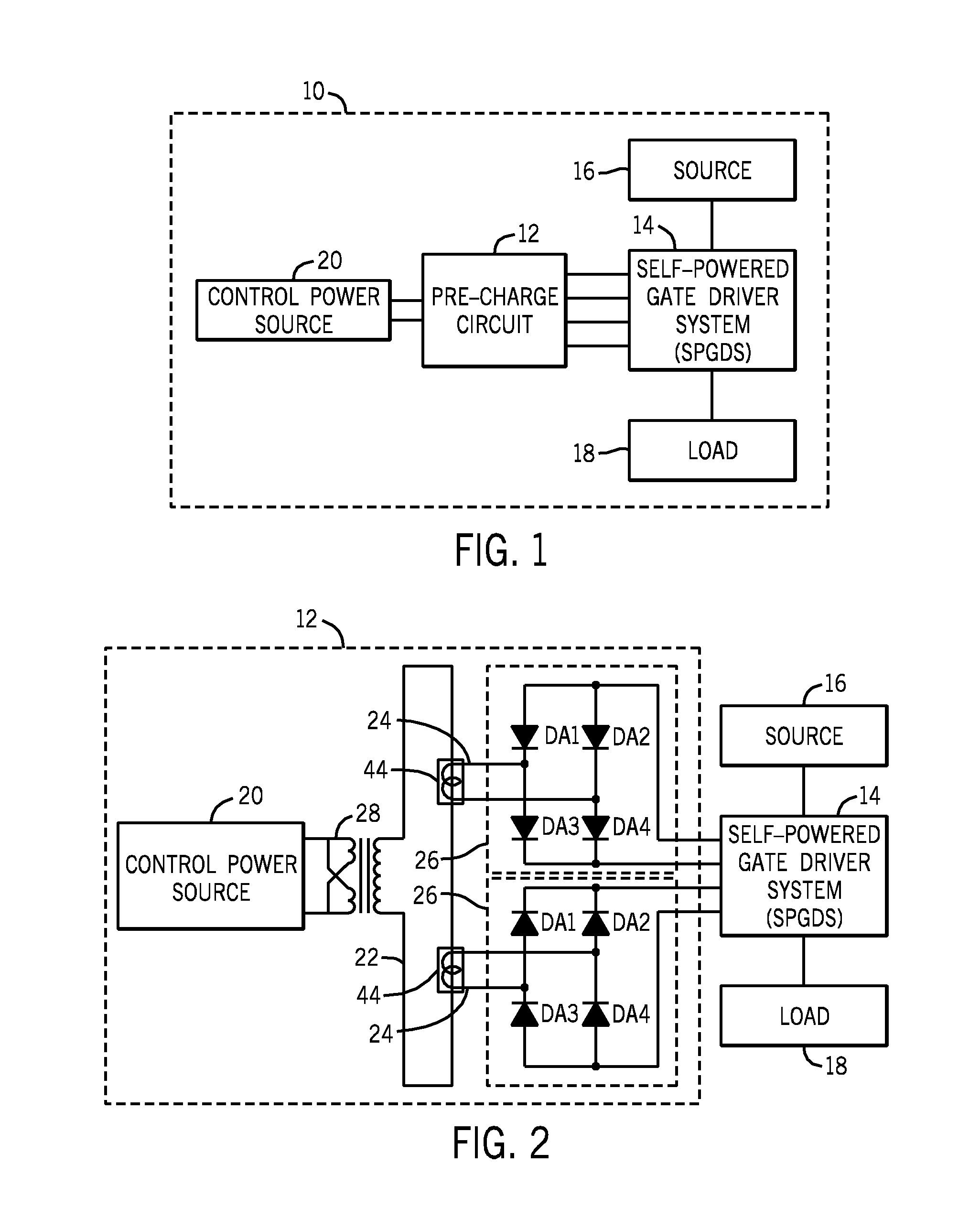
[0018]As described above, SPGDSs capture energy from a power supply driving a load using a series of capacitors connected to self-powered circuitry. More specifically, the SPGDSs draw current and store charge through voltage differentials across SCRs. The stored charge may then be used to power drivers of the SPGDSs. However, as also described above, SPGDSs are in need of improvement because it is now recognized that SPGDSs are associated with delays in operation and response time. When transitioning from certain modes of operation, the capacitors may lack enough charge to power the drivers. Consequently, a re-activated SPGDS may exhibit a delay before conducting current as the capacitors charge over a few cycles. For example, during full speed operation, some systems bypass the SCRs to deliver power directly from the power supply to the motor. Without a voltage differential across the SCRs, the capacitors may discharge, leaving the drivers without a source of power. Thus, when such...


PUM


Abstract

The present invention relates generally to systems and methods for isolating a current loop conductor of a current loop system of a pre-charge circuit from a plurality of current transformers disposed around the current loop conductor. In particular, the embodiments described herein include an insulating support flange having a first tubular section, a second tubular section radially disposed around the first tubular section and connected to the first tubular section via a solid annular section extending radially outward from the first tubular section to a first end of the second tubular section, an annular base extending radially outward from a second end of the second tubular section, and a plurality of prongs extending axially from or near to an outer circumference of the annular base, wherein each of the prongs comprises an end face that is angled toward the second tubular section. The insulating support flanges are configured to mate with each other along an axial direction of the current loop conductor. In addition, each of the plurality of current transformers is installed (i.e., held in place) between the prongs, annular base, and second annular section of its respective insulating support flange. As such, a fixed open air space between the first and second annular sections of the insulating support flanges isolates the current transformers from the current loop conductor, thereby reducing the possibility of discharge between the current transformers and the current loop conductor.

Description

BACKGROUND[0001]The invention relates generally to the field of power control systems. More specifically, the invention relates to an insulating support flange for eliminating partial discharge in a current loop system.[0002]Motor controllers, and more generally, electrical controllers operate by limiting the power from a power supply that reaches a motor or other load. For example, some motor controllers limit the power delivered to a motor by intermittently conducting current between the power supply and the motor. These motor controllers typically couple to a sinusoidal alternating current (AC) power supply and conduct current during a portion of each cycle of the sinusoid. Correspondingly, to limit the power delivered to the motor, the motor controller may not conduct current during a portion of each cycle. Typically, the duration of the period during which the motor controller does not conduct current is adjustable. Consequently, by adjusting the duration of this non-conductive...

Claims


Application Information

Patent Timeline
IPC IPC(8): H01F38/28H01B17/00
CPCH01F38/28H01F27/06H03K2217/0081H01F30/04H01F2038/305H01F27/324
Inventor MACLENNAN, DAVID SCOTTWENTZELL, MARIANA
Owner ROCKWELL AUTOMATION TECH
Why Eureka
Eureka Blog
Learn More