
Compact holographic edge illuminated eyeglass display

a display and holographic edge technology, applied in the field of wearable display devices, can solve the problems of cumbersome form factors, insufficient, and current wearable displays only manage to deliver see through, and achieve the effect of minimizing laser speckl

Active Publication Date: 2012-08-30
DIGILENS +1
View PDF1 Cites 139 Cited by
  • Summary
  • Abstract
  • Description
  • Claims
  • Application Information

AI Technical Summary

Benefits of technology

[0014]In a further embodiment of the invention there is provided a wearable display comprising a light-guide forming one transparent substrate of an HPDLC cell and a DOE forming the second substrate and further comprising a laser illuminator. The laser illuminator comprises red, green and blue laser sources, a beam combiner and expander, a means for minimizing laser speckle and a means for coupling illumination to the curved light guide.

Problems solved by technology

The above goals are not achieved by current technology.
Current wearable displays only manage to deliver see through, adequate pupils, eye relief and field of view and high brightness simultaneously at the expense of cumbersome form factors.
In many cases weight is distributed in the worst possible place for a wearable display, in front of the eye.
Microdisplays, which provide high-resolution image generators in tiny flat panels, do not necessarily help with miniaturizing wearable displays because the requirement for very high magnifications inevitably results in large diameter optics.
Several ultra low form factor designs offering spectacle-like form factors are currently available but usually require aggressive trade-offs against field of view, eye relief and exit pupil.
A Bragg grating is then recorded by illuminating the liquid material with two mutually coherent laser beams, which interfere to form the desired grating structure.
When an electric field is applied to the hologram via the electrodes, the natural orientation of the LC droplets is changed thus reducing the refractive index modulation of the fringes and causing the hologram diffraction efficiency to drop to very low levels.

Method used


Image

  • Compact holographic edge illuminated eyeglass display
  • Compact holographic edge illuminated eyeglass display
  • Compact holographic edge illuminated eyeglass display

Examples


Embodiment Construction

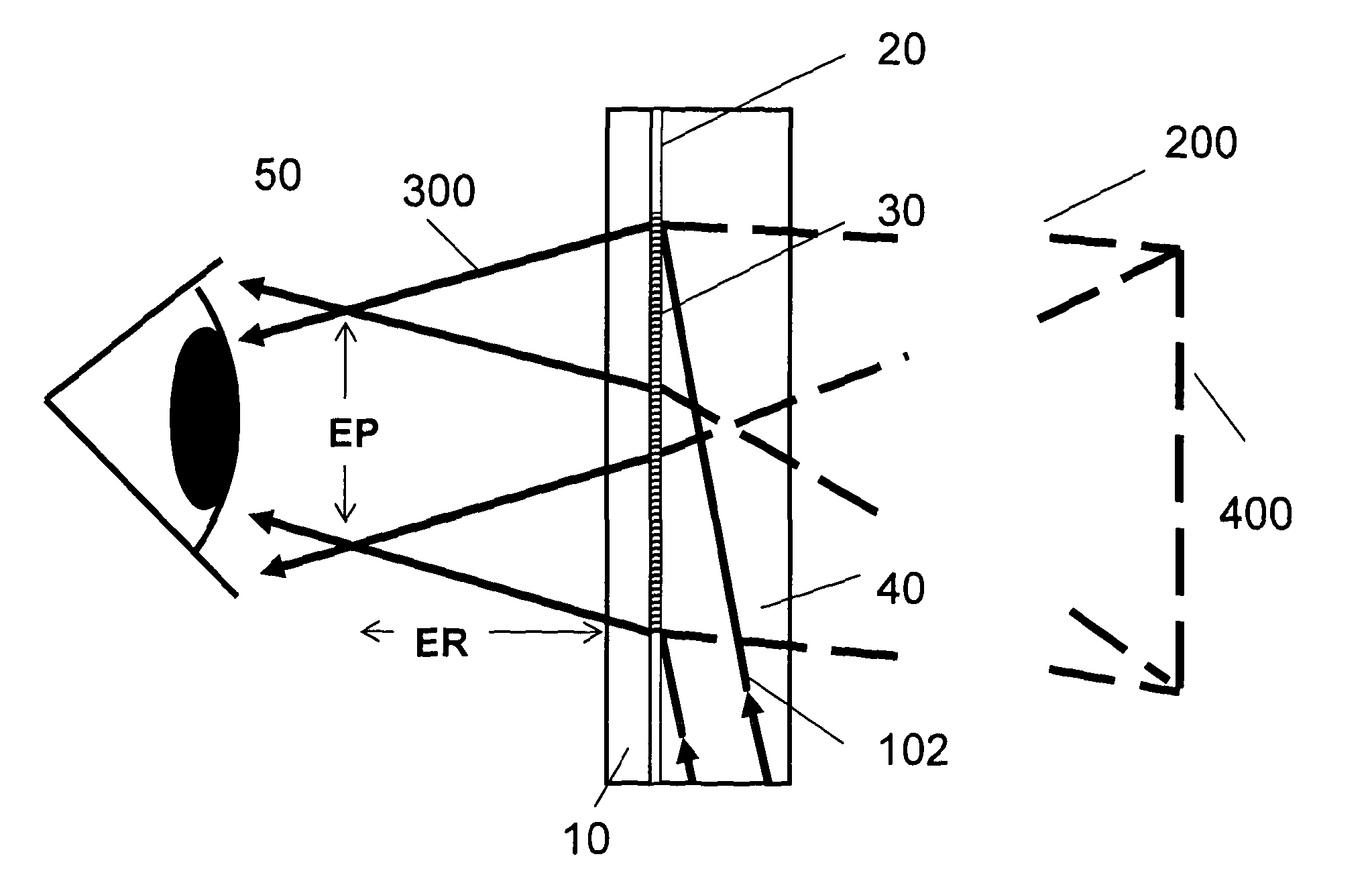
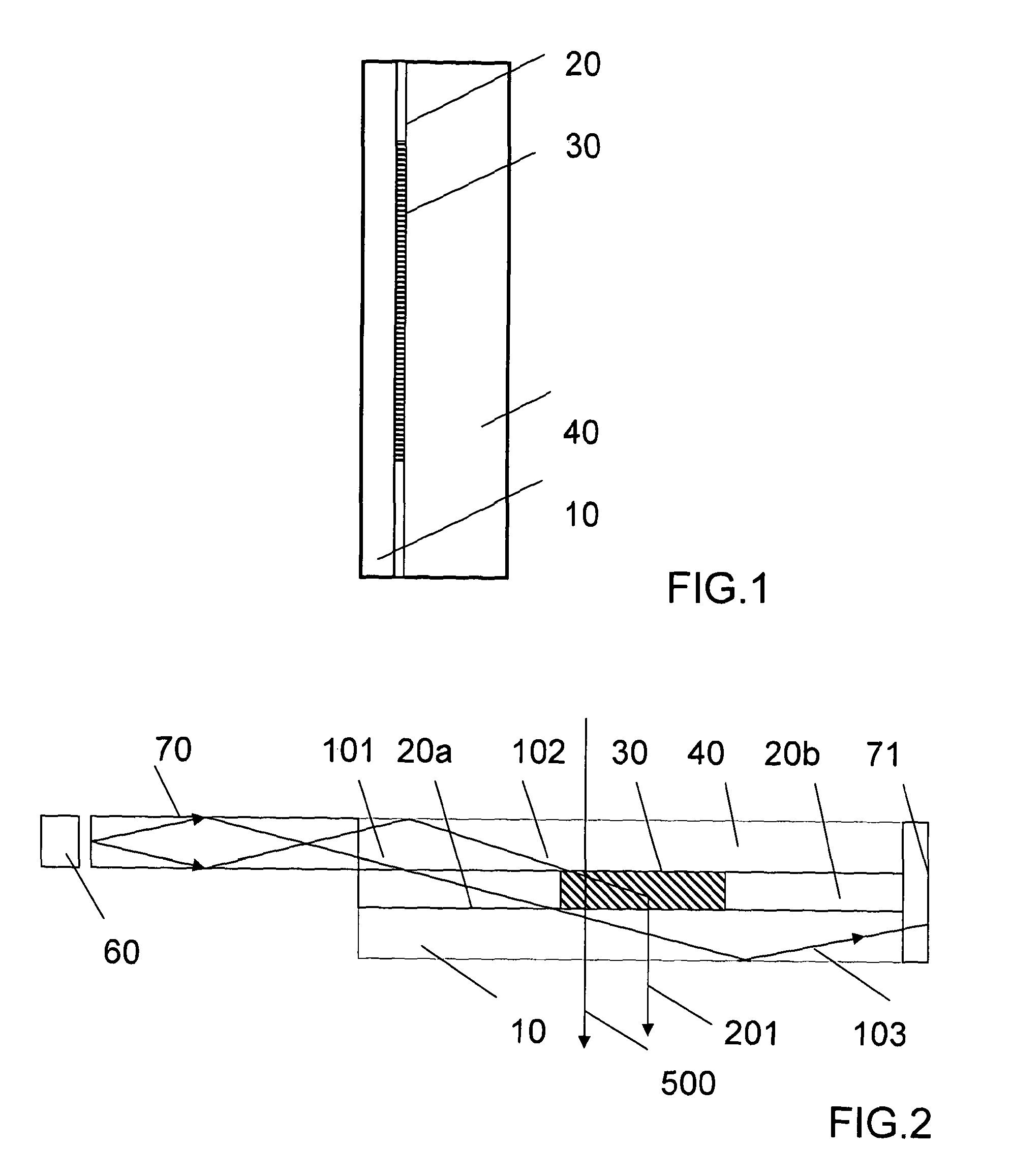
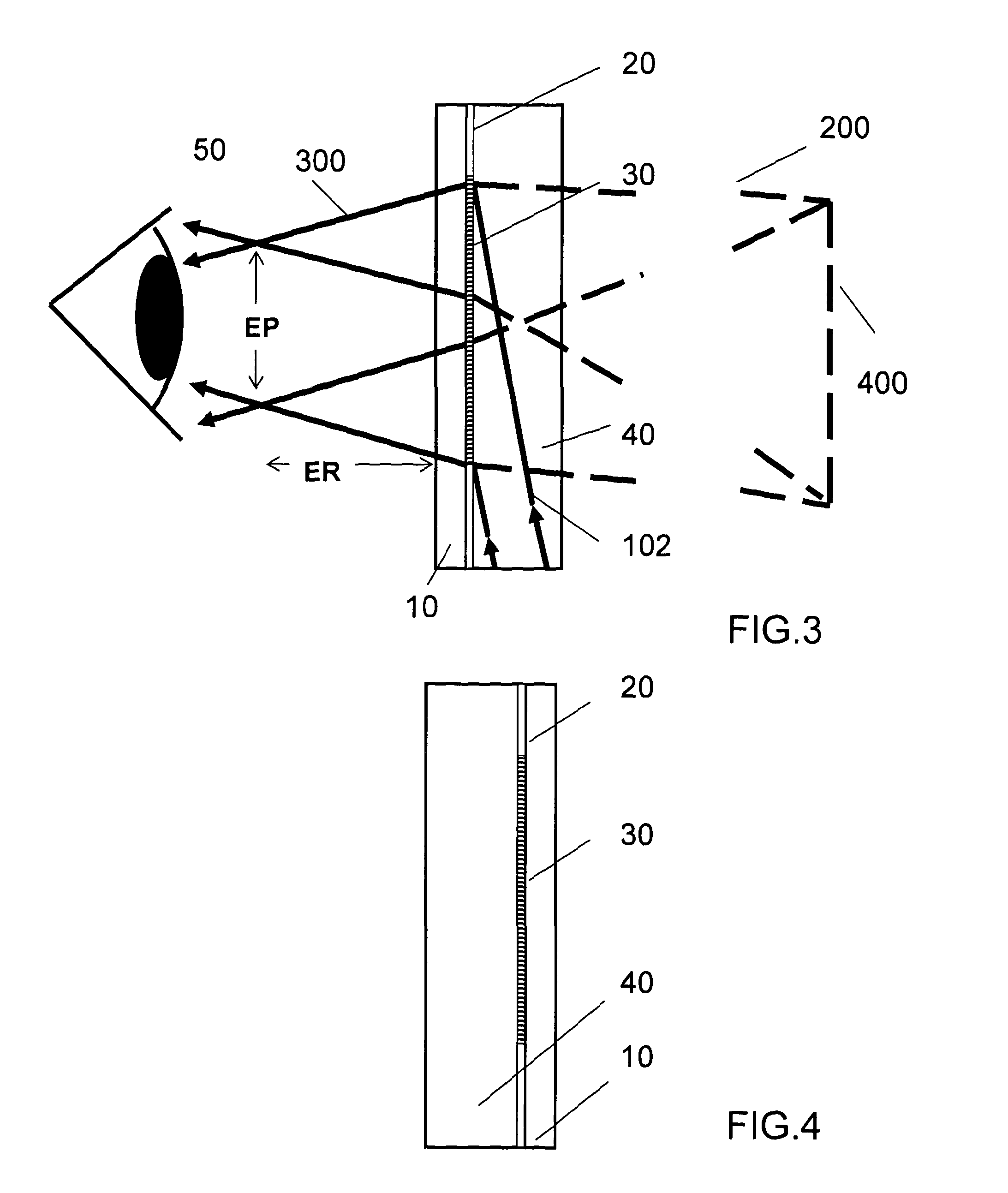
[0082]The invention will now be further described by way of example only with reference to the accompanying drawings.

[0083]It will apparent to those skilled in the art that the present invention may be practiced with some or all of the present invention as disclosed in the following description. For the purposes of explaining the invention well-known features of optical technology known to those skilled in the art of optical design and visual displays have been omitted or simplified in order not to obscure the basic principles of the invention.

[0084]Unless otherwise stated the term “on-axis” in relation to a ray or a beam direction refers to propagation parallel to an axis normal to the surfaces of the optical components described in relation to the invention. In the following description the terms light, ray, beam and direction may be used interchangeably and in association with each other to indicate the direction of propagation of light energy along rectilinear trajectories.

[0085...


PUM

PropertyMeasurementUnit
Transparencyaaaaaaaaaa
Wavelengthaaaaaaaaaa
Electric fieldaaaaaaaaaa

Abstract

There is provided a wearable display comprising at least one Switchable Bragg Grating (SBG) device recorded in at least one Holographic Polymer Dispersed Liquid Crystal (HPDLC) layer. Each HPDLC layer is sandwiched between first and second transparent plates to which transparent electrodes have been applied. Each SBG device is characterised in that it provides a grating in a separate switchable region and is clear elsewhere. Each SBG device has a diffracting state and a non diffracting state. The transparent plates and HPDLC layers form a laminar structure which functions as a light guide. In one embodiment of the invention the display magnifies and forms a virtual image of information provided by an external image generator. In one embodiment of the invention the display and forms a virtual image of an image of information encoded in the SBG device.

Description

REFERENCE TO EARLIER APPLICATIONS[0001]This application claims the priority of U.S. Provisional Patent Application No. 61 / 272,734 filed on 27 Oct. 2009 entitled COMPACT HOLOGRAPHIC EDGE ILLUMINATED EYEGLASS DISPLAY which is incorporated herein by reference in its entirety.[0002]This application incorporates by reference in its entirety PCT Application US2008 / 001909, with International Filing Date: 22 Jul. 2008, entitled LASER ILLUMINATION DEVICE, U.S. patent application Ser. No. 10 / 555,661 filed 4 Nov. 2005 entitled SWITCHABLE VIEWFINDER DISPLAY and PCT Application No. US2006 / 043938, claiming priority to U.S. provisional patent application 60 / 789,595 filed on 6 Apr. 2006, entitled METHOD AND APPARATUS FOR PROVIDING A TRANSPARENT DISPLAY,BACKGROUND OF THE INVENTION[0003]This invention relates to a wearable display device, and more particularly to a wearable display using electrically switchable holographic optical elements.[0004]There is a requirement for a compact see through data d...

Claims


Application Information

Patent Timeline
IPC IPC(8): G02F1/1335
CPCG02B5/1819G02B27/017G02B5/203G02B5/32G02B27/0172G02F1/13342G02F1/133615G02F1/133621G02F1/134309G02F1/13473G02B6/0028G02F2001/13775G02F2201/123G02F2201/30G02F2201/307G02F2203/12G02F2203/62G02B5/1842G02F1/13775
Inventor POPOVICH, MILAN MOMCILOWALDERN, JONATHAN DAVID
Owner DIGILENS
Learn More