Image processing device, imaging system, image processing method, and program for causing computer to perform image processing

Active Publication Date: 2012-08-30
CANON KK
View PDF2 Cites 32 Cited by
  • Summary
  • Abstract
  • Description
  • Claims
  • Application Information

AI Technical Summary

Problems solved by technology

However, SLO images focused near visual cells do not always allow accura

Method used


Image

  • Image processing device, imaging system, image processing method, and program for causing computer to perform image processing
  • Image processing device, imaging system, image processing method, and program for causing computer to perform image processing
  • Image processing device, imaging system, image processing method, and program for causing computer to perform image processing

Examples


Embodiment Construction

[0022]Various exemplary embodiments, and features will be described in detail below with reference to the drawings.

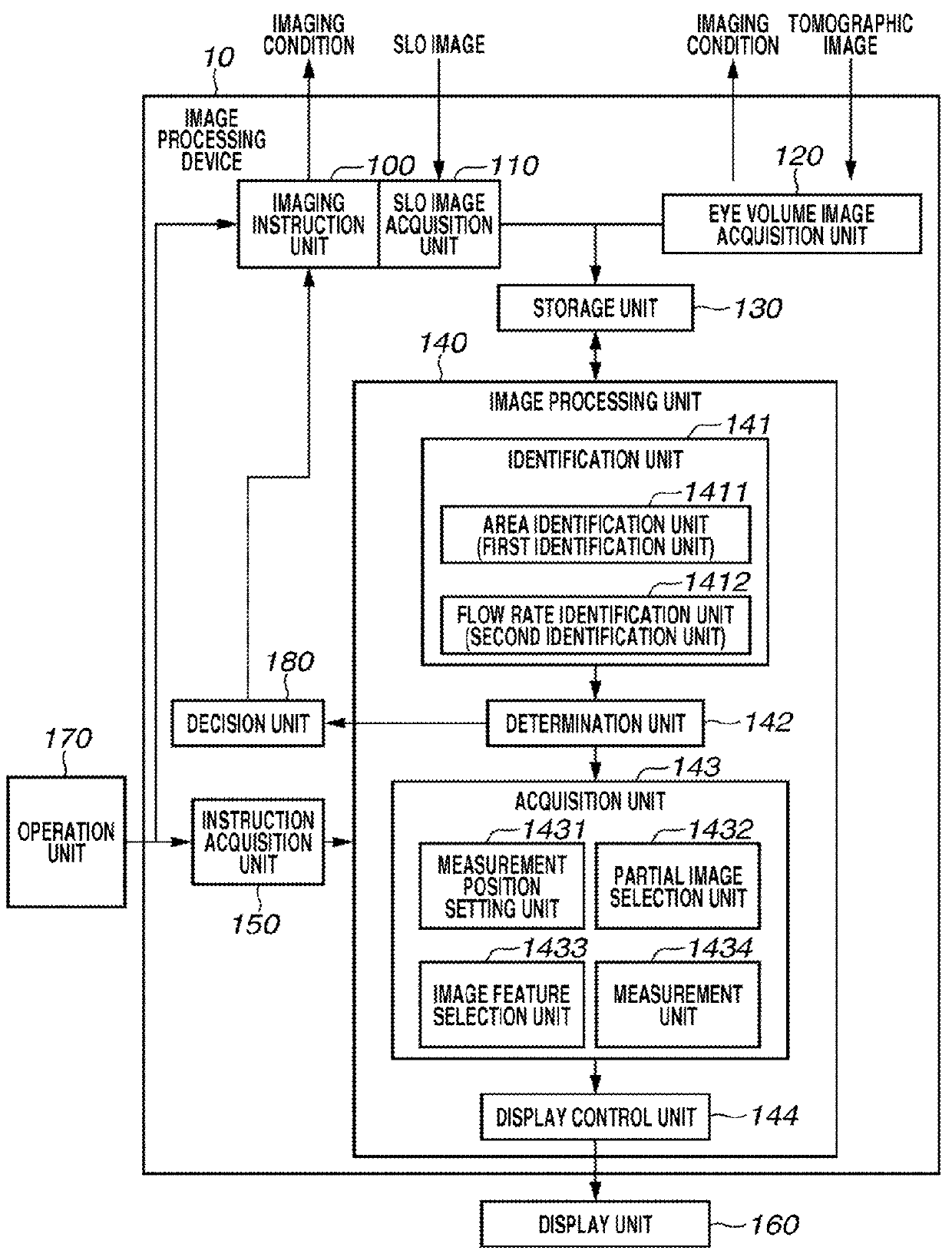
[0023]Referring to FIG. 1, the functional configuration of an image processing device 10 according to the present first exemplary embodiment will be described. FIG. 1 is a block diagram illustrating the functional configuration of the image processing device 10. The image processing device 10 include an imaging instruction unit 100, an SLO image acquisition unit 110, an eye volume image acquisition unit 120, a storage unit 130, an image processing unit 140, and an instruction acquisition unit 150. A display unit 160 and an operation unit 170 are connected to the image processing device 10.

[0024]The image processing unit 140 includes an identification unit 141, a decision unit 142, an acquisition unit 143, a display control unit 144, and a determination unit 180. The image processing unit 140 processes images of an eye, which is an object to be imaged. The identification...


PUM


Abstract

An image processing device includes a first identification unit configured to identify the spatial configuration of a vessel in an object to be imaged, a second identification unit configured to identify information on a blood flow rate of the vessel based on an SLO moving image obtained by signal light that has a focus position deeper than at least a part of the area of the vessel, and an acquisition unit configured to acquire information on a blood flow of the vessel based on the identified area and the information on the blood flow rate.

Description

BACKGROUND OF THE INVENTION[0001]1. Field of the Invention[0002]The present disclosure relates to image processing for processing eye images.[0003]2. Description of the Related Art[0004]An eye examination is widely practiced for early diagnosis of lifestyle related diseases and diseases that rank high among the leading causes of blindness. A scanning laser ophthalmoscope (SLO), hereinafter referred to as an SLO imaging device, is an ophthalmologic instrument that uses the principles of a confocal laser microscope. An SLO imaging device performs raster scanning of the fundus with measurement laser light and acquires a planar image of the retina from the intensity of return light with high resolution and high speed.[0005]There have been developed some SLO imaging devices that have an adaptive optics (AO) system for measuring aberrations of the eye to be examined with a wavefront sensor and correcting aberrations of measurement light occurring in the eye to be examined and aberrations ...

Claims


Application Information

Patent Timeline
IPC IPC(8): A61B3/14G06K9/00
CPCA61B3/1241A61B3/1025
Inventor IMAMURA, HIROSHI
Owner CANON KK
Why Eureka
Try Eureka