Method and device for aggregating a plurality of service data from machine terminal equipment

a terminal equipment and service data technology, applied in the field of radio network, can solve the problems of low amount of service data, low amount of actual transmitted data, and low complexity of transmitting service data, so as to save radio resources in the radio access network, shorten the period of time, and save power consumption of the terminal equipment

Inactive Publication Date: 2012-08-30
ALCATEL LUCENT SAS
View PDF15 Cites 14 Cited by
  • Summary
  • Abstract
  • Description
  • Claims
  • Application Information

AI Technical Summary

Benefits of technology

[0019]With the solution of the invention, a signaling overhead and thus radio resources in a radio access network can be saved, and preferably the technical solution of the invention also shortens a period of time for a terminal equipment to wait for a feedback so that the terminal equipment can enter a dormancy status or transmit new service data as soon as possible, thereby saving power consumption of the terminal equipment.

Problems solved by technology

However the amount of uplink service data transmitted by general M2M terminal equipment is typically low in M2M communication, and such signaling interaction in an existing communication system may not be suitable for M2M communication due to a considerable overhead and an increase in the complexity of transmitting service data.
Therefore a plurality of handshakes at different peer layers are required, but the amount of actually transmitted data, i.e., the amount of service data, is very low.
Thus there is considerable redundancy resulting from uplink transmission of the terminal equipment.
In other words, the existing network architecture is very uneconomic for M2M communication.
Therefore the terminal equipment 1 has to keep awake for a long period of time which consumes power on one hand and is required to receive and transmit more redundant signaling messages in this network architecture on the other hand.

Method used


Image

  • Method and device for aggregating a plurality of service data from machine terminal equipment
  • Method and device for aggregating a plurality of service data from machine terminal equipment
  • Method and device for aggregating a plurality of service data from machine terminal equipment

Examples


Embodiment Construction

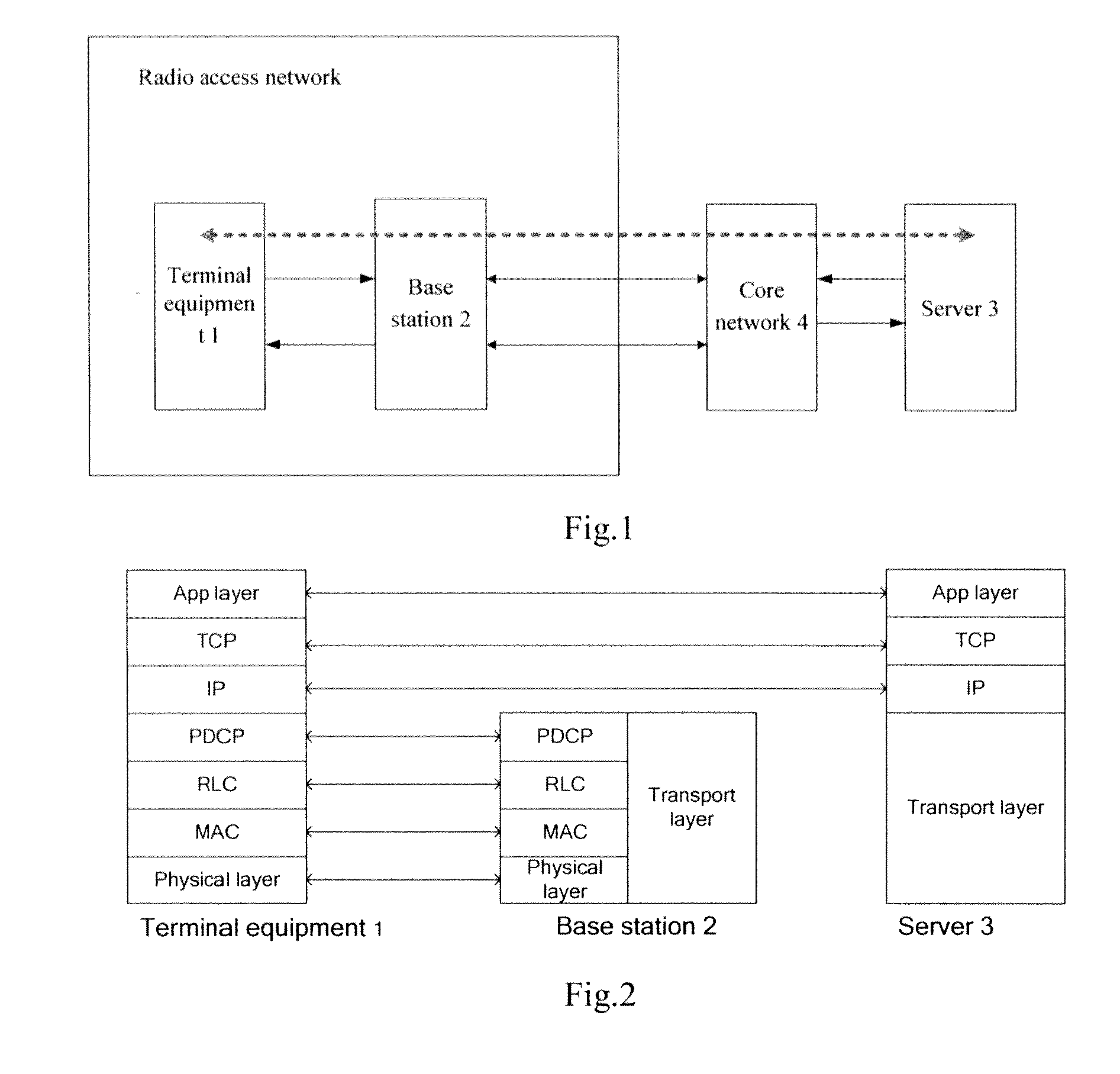
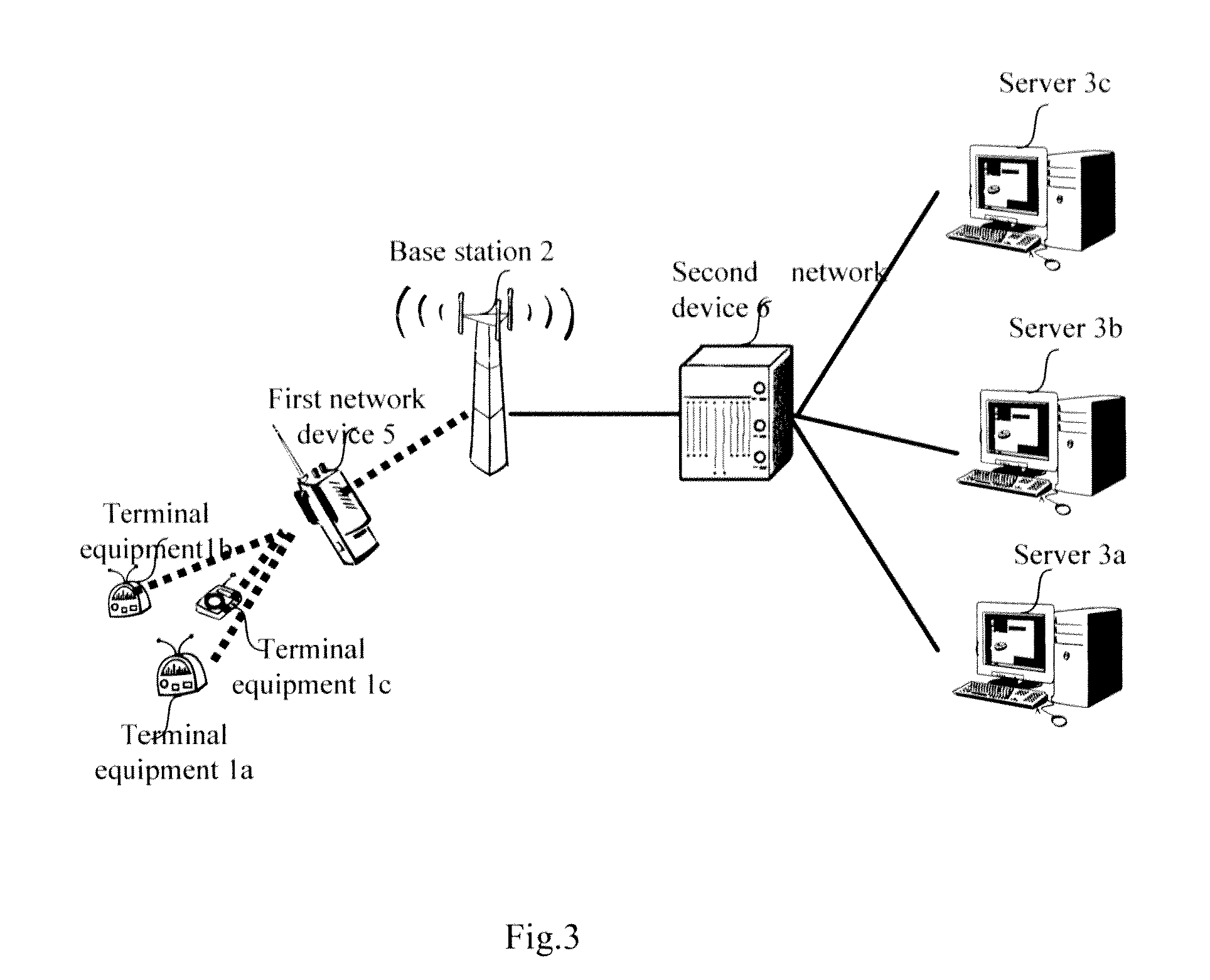
[0029]FIG. 3 illustrates a schematic structural diagram of a network topology according to an embodiment of the invention. The terminal equipment 1, particularly represented as terminal equipments 1a, 1b and 1c in FIG. 3, includes a Bluetooth terminal equipment, an infrared terminal equipment, a Zigbee protocol based radio terminal equipment or other 3GPP communication protocol based or non-3GPP communication protocol based radio terminal equipment. Only three terminal equipments 1a, 1b and 1c are illustrated in FIG. 3 as a non-limiting example, and the number of terminal equipments will not be limited thereto in a practical network. As compared with the schematic structural diagram of the network architecture of the existing communication system illustrated in FIG. 1, a first network device 5 and a second network device 6 are added in the schematic structural diagram of the network topology according to the embodiment of the invention illustrated in FIG. 3. Particularly the first n...


PUM


Abstract

The invention proposes a method and device for aggregating a plurality of service data from a terminal equipment. A first network device in a radio access network encapsulates a plurality of service data from a machine terminal equipment into a non-access stratum data packet, performs a transmission process on the non-access stratum data packet to generate a processed signal and transmits the processed signal; and the signal is forwarded by a base station to a second network device in a core network, and the second network device recovers the non-access stratum data packet from the signal, extracts the plurality of service data from the non-access stratum data packet and then transmits the plurality of service data respectively to a corresponding destination server. With the solution of the invention, a signaling overhead and thus radio resources in a radio access network can be saved, and preferably a period of time for a terminal equipment to wait for a feedback can also be shorten so that the terminal equipment can enter a dormancy status or transmit new service data as soon as possible, thereby saving power consumption of the terminal equipment.

Description

FIELD OF THE INVENTION[0001]The present invention relates to a radio network and particularly to an operation of a network device for aggregating service data from a terminal equipment.BACKGROUND OF THE INVENTION[0002]Traditional communication involving a person is characterized in an unspecific operating application. For example, a user chooses to browse a webpage, to play a video, etc., through an input device, e.g., a keyboard, a mouse, a tablet, etc., of a terminal equipment and thus initiates a variety of applications. Correspondingly, Machine to Machine Communication (M2M) is data communication, conducted between entities, in which interaction with a person may not necessarily be required. M2M communication differs from an existing human-machine interaction model in that:[0003]There is a new or different market prospect of applications;[0004]There is a lower cost;[0005]There are a large number of potential machine communication terminal equipments; and[0006]The majority of tra...

Claims


Application Information

Patent Timeline
Patent Type & Authority Applications(United States)
IPC IPC(8): H04W4/00H04W72/04H04W4/70
CPCH04W4/005H04W8/24H04W72/0406Y02B60/50H04W28/065H04W4/70Y02D30/70H04L5/0044H04W72/20
Inventor CHEN, YU
Owner ALCATEL LUCENT SAS
Why Eureka
Try Eureka