Supercharge Your Innovation With Domain-Expert AI Agents!

Cutter body and locking screw therefor

a technology of locking screw and cutter body, which is applied in the direction of shaping cutter, tool workpiece connection, manufacturing tools, etc., can solve problems such as premature tool failur

Inactive Publication Date: 2012-08-30
KENNAMETAL INC
View PDF2 Cites 2 Cited by
  • Summary
  • Abstract
  • Description
  • Claims
  • Application Information

AI Technical Summary

Benefits of technology

[0002]The invention solves the problem associated with the thin, weak cross-section between the insert pockets and the counterbore of the locking screw in conventional designs by eliminating the counter bore for the locking screw. The invention also permits the use of a standard milling adapter because elements of the invention reside in the cutter body.

Problems solved by technology

Typically, the thin cross-sectional area 106 exhibits high stresses during a machining operation, which can lead to cracking and premature tool failure.

Method used


Image

  • Cutter body and locking screw therefor
  • Cutter body and locking screw therefor
  • Cutter body and locking screw therefor

Examples


Embodiment Construction

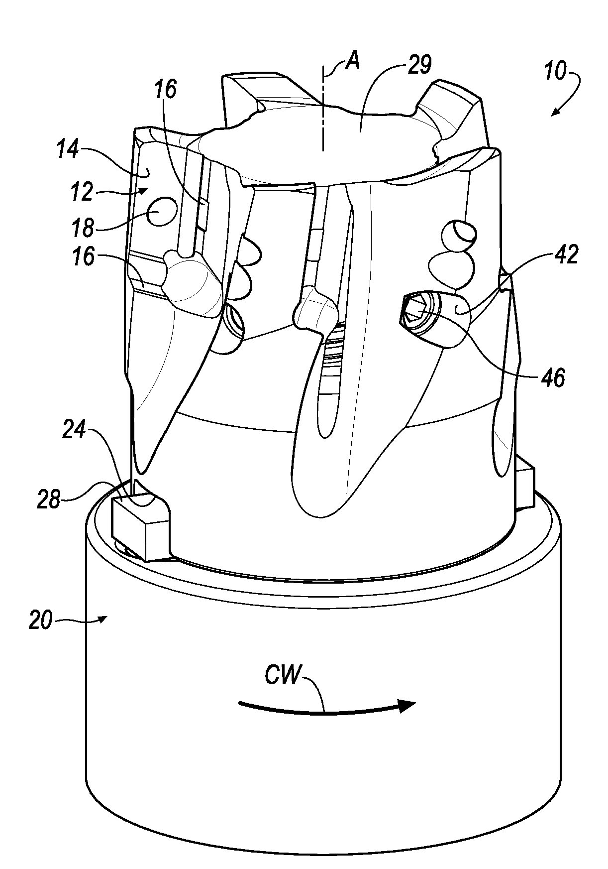
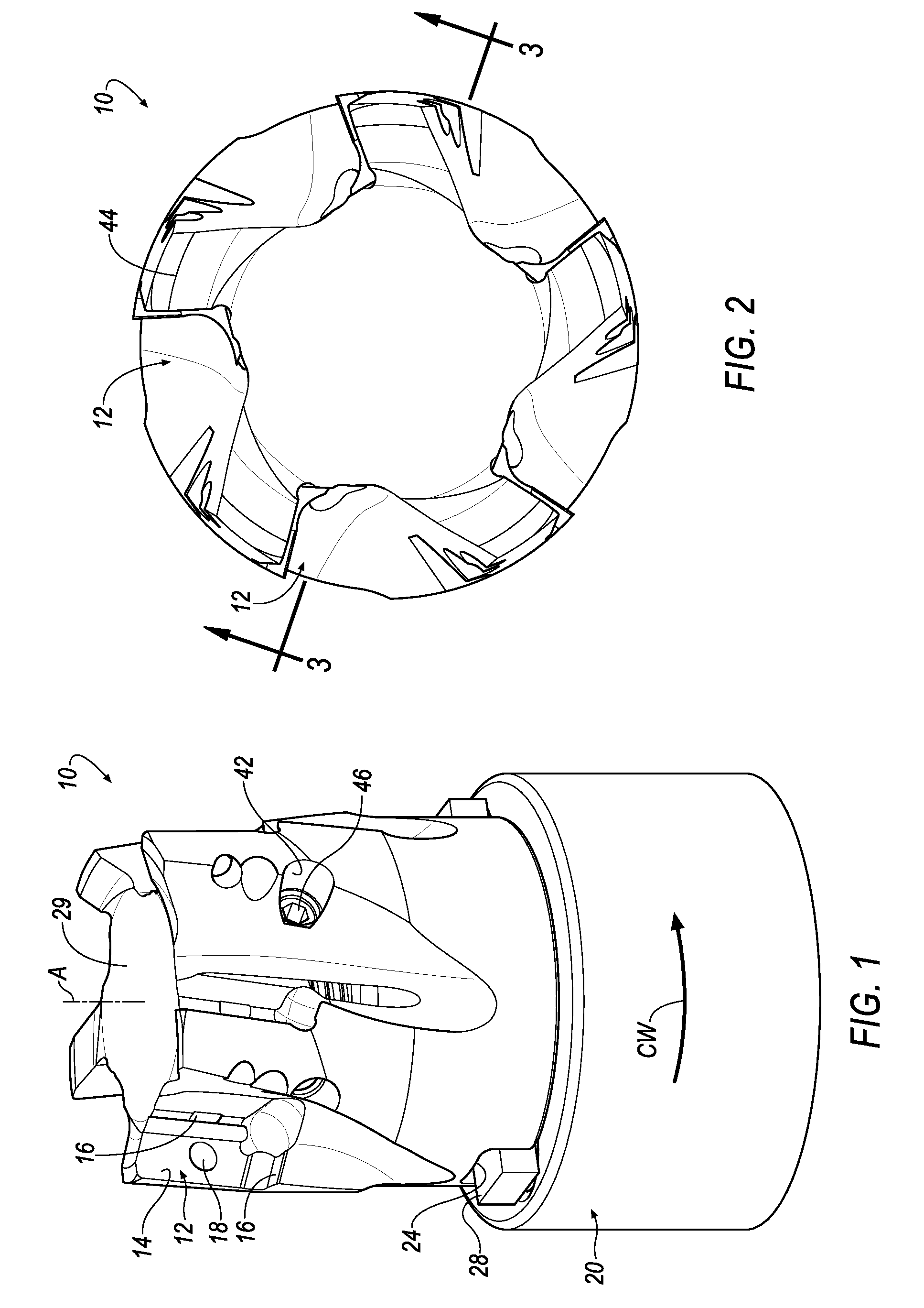
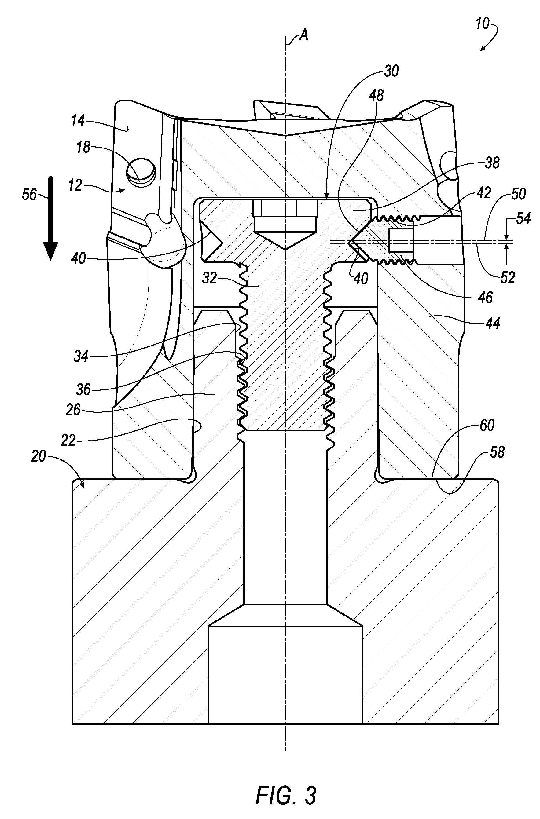
[0011]With reference now to the drawings, wherein like numerals designate like components throughout all of the several figures, there is illustrated in FIGS. 1-3 a cutter body, as generally indicated at 10. The cutter body 10 shown is particularly suited for shell milling operations. However, the cutter body 10 may take on other forms suitable for other metalworking operations.

[0012]The cutter body 10 comprises one or more pockets 12 formed therein. The pockets 12 in the illustrated cutter body 10 are arranged axially and circumferentially in an angularly spaced relation to each other. Each pocket 12 is provided for receiving a cutting insert (not shown). Each pocket 12 comprises a substantially planar seat or base 14 and two shoulders 16. The relative angles formed by the shoulders 16 with respect to the base 14 and to each other are not important to the invention, and can be formed at any desirable relative angle. Each shoulder 16 provides a surface that abuts a corresponding sur...


PUM

PropertyMeasurementUnit
circumferenceaaaaaaaaaa
distanceaaaaaaaaaa
shapeaaaaaaaaaa

Abstract

A combination cutter body and a locking screw for mounting the cutter body to an adapter is disclosed. The cutter body includes a plurality of threaded bores that extend radially through a sidewall of the cutting body. The threaded bores are adapted to receive a corresponding threaded setscrew. The locking screw includes a head having a plurality of indentations around a circumference of the head. A central axis of each threaded bore is offset by a distance from a central axis of each indentation to cause an axial force to be exerted on the cutter body when an end of the setscrew engages a respective indentation to tightly seat the cutter body against the adapter.

Description

BACKGROUND OF THE INVENTION[0001]When milling cutter with small cutting diameters are designed with cap screw style (A-style) shell mill mountings, a thin, weak cross-sectional area 106 usually occurs in a cutter body 100 between the insert pockets (and chip gashes) 102 and the counter bore 104 for the locking screw, as shown in FIG. 5. Typically, the thin cross-sectional area 106 exhibits high stresses during a machining operation, which can lead to cracking and premature tool failure. It would be desirable to eliminate the thin, weak cross-sectional area that exists in conventional designs.SUMMARY OF THE INVENTION[0002]The invention solves the problem associated with the thin, weak cross-section between the insert pockets and the counterbore of the locking screw in conventional designs by eliminating the counter bore for the locking screw. The invention also permits the use of a standard milling adapter because elements of the invention reside in the cutter body.[0003]In one aspec...

Claims


Application Information

Patent Timeline
Patent Type & Authority Applications(United States)
IPC IPC(8): B23C5/22B23P11/00
CPCB23C5/26Y10T29/49963Y10T407/192B23C2240/24B23B31/1076Y10T409/30952B23C5/10Y10T407/1934B23C2210/02
Inventor GAMBLE, KEVIN MICHAEL
Owner KENNAMETAL INC
Features
  • R&D
  • Intellectual Property
  • Life Sciences
  • Materials
  • Tech Scout
  • Unparalleled Data Quality
  • Higher Quality Content
  • 60% Fewer Hallucinations
Learn More