Non-cavitation shockwave balloon catheter system

a balloon catheter and shockwave technology, applied in the field of non-cavitation shockwave balloon catheter system, can solve the problem of generating a mild shockwav

Active Publication Date: 2012-08-30
SHOCKWAVE MEDICAL
View PDF8 Cites 129 Cited by
  • Summary
  • Abstract
  • Description
  • Claims
  • Application Information

AI Technical Summary

Benefits of technology

[0005]The first and second shock waves have energies and the energy of the first shock wave may be greater than the energy of the second shock wave. The shock wave generator is preferably arranged to form a bubble that is non-symmetrical in configuration or contains a structure, such as a guide wire lumen sheath, in the center line of the bubble. It is especially preferab...

Problems solved by technology

Bubbles in a balloon that are symmetrical ...

Method used


Image

  • Non-cavitation shockwave balloon catheter system
  • Non-cavitation shockwave balloon catheter system
  • Non-cavitation shockwave balloon catheter system

Examples


Embodiment Construction

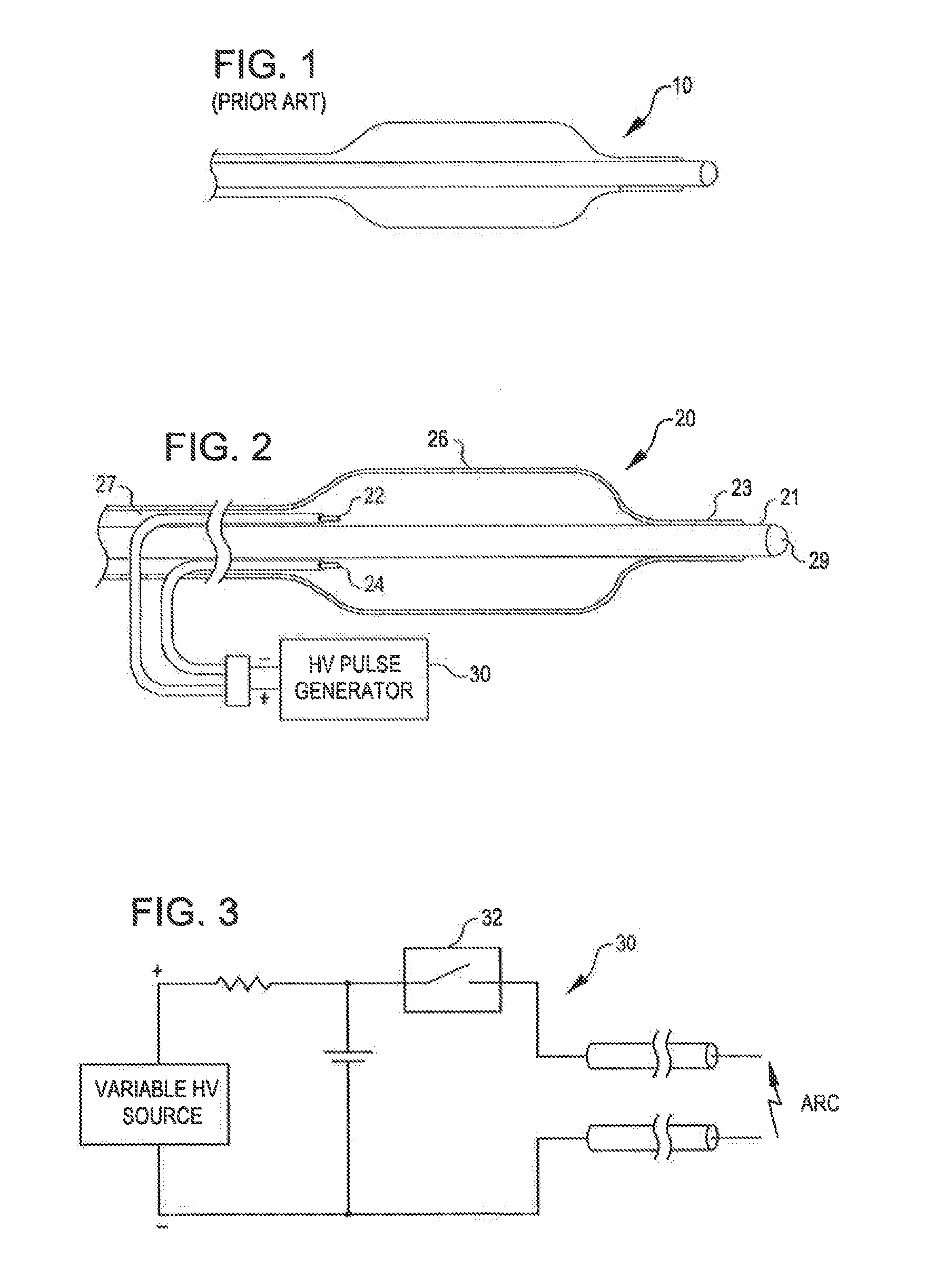
[0036]FIG. 1 is a view of the therapeutic end of a typical prior art over-the-wire angioplasty balloon catheter 10. Such catheters are usually non-complaint with a fixed maximum dimension when expanded with a fluid such as saline.

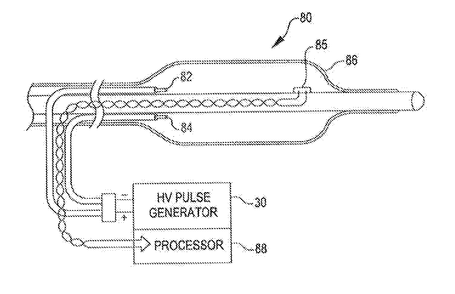
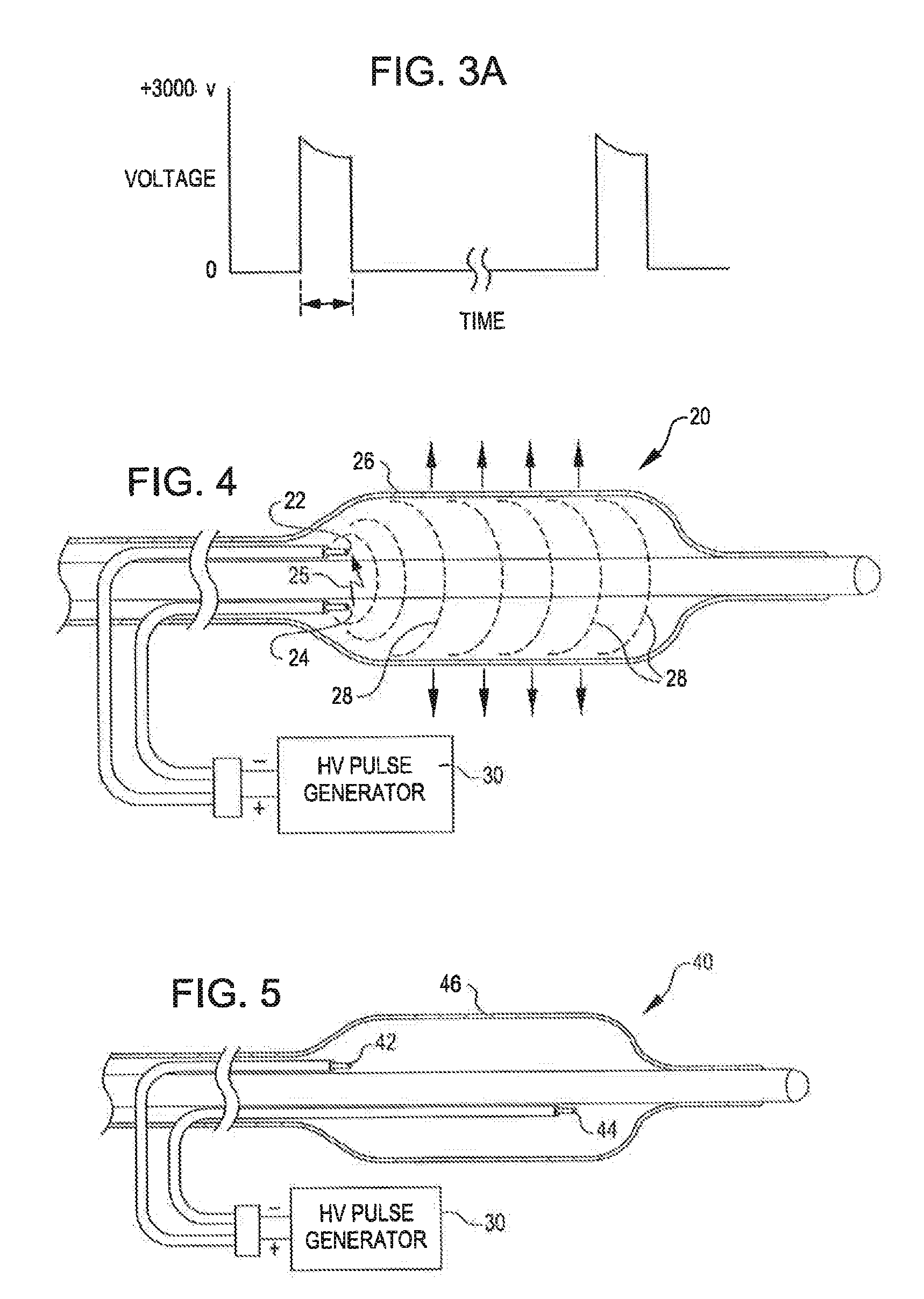
[0037]FIG. 2 is a view of a dilating angioplasty balloon catheter 20 according to an embodiment of the invention. The catheter 20 includes an elongated carrier, such as a hollow sheath 21, and a dilating balloon 26 formed about the sheath 21 in sealed relation thereto at a seal 23. The balloon 26 forms an annular channel 27 about the sheath 21 through which fluid, such as saline, may be admitted into the balloon to inflate the balloon. The channel 27 further permits the balloon 26 to be provided with two electrodes 22 and 24 within the fluid filled balloon 26. The electrodes 22 and 24 are attached to a source of high voltage pulses 30. The electrodes 22 and 24 are formed of metal, such as stainless steel or tungsten, and are placed a controlled distance apa...


PUM


Abstract

An angioplasty catheter includes an elongated carrier, and an angioplasty balloon about the carrier in sealed relation thereto. The balloon is arranged to receive a fluid therein that inflates the balloon. The catheter further includes a shock wave generator within the balloon that forms a rapidly expanding and collapsing bubble within the balloon to form mechanical shock waves within the balloon. The expanding bubble forms a first shock and the collapsing balloon forms a second shock wave. The shock wave generator is arranged such that the energy of the first shock wave is greater than the energy of the second shock wave.

Description

CROSS-REFERENCE TO RELATED APPLICATION[0001]This application is a continuation-in-part of U.S. application Ser. No. 12 / 482,995 filed on Jun. 11, 2009 (pending), which application claims the benefit of priority to U.S. Provisional Application No. 60 / 061,170 filed on Jun. 13, 2008, all of which applications are incorporated herein by reference in their entireties for all purposes.BACKGROUND OF THE INVENTION[0002]The present invention relates to a treatment system for percutaneous coronary angioplasty or peripheral angioplasty in which a dilation catheter is used to cross a lesion in order to dilate the lesion and restore normal blood flow in the artery. It is particularly useful when the lesion is a calcified lesion in the wall of the artery. Calcified lesions require high pressures (sometimes as high as 10-15 or even 30 atmospheres) to break the calcified plaque and push it back into the vessel wall. With such pressures comes trauma to the vessel wall which can contribute to vessel r...

Claims


Application Information

Patent Timeline
IPC IPC(8): A61B17/22
CPCA61B17/2202A61B17/22022A61B2017/22025A61B17/320725A61B2017/22024A61B17/2251
Inventor HAWKINS, DANIELALFERNESS, CLIFTON A.ADAMS, JOHN M.
Owner SHOCKWAVE MEDICAL
Why Eureka
Try Eureka