
Signal processing circuit, image scanner, and image forming apparatus

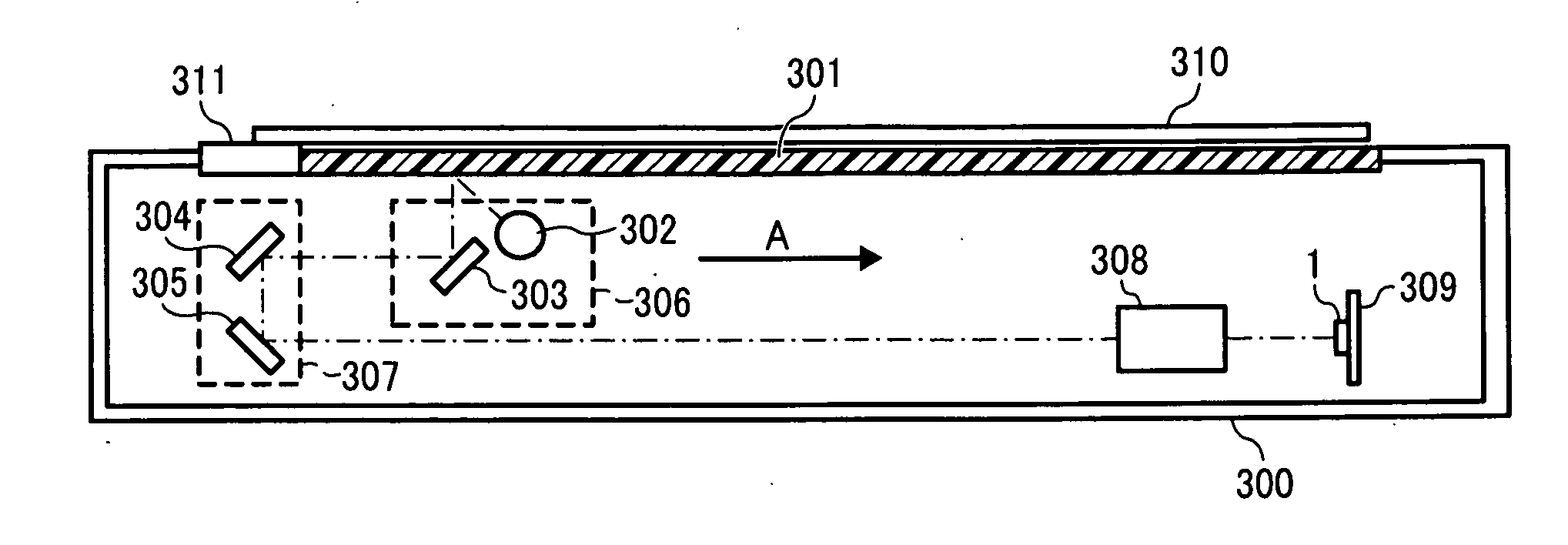
a technology of image scanner and processing circuit, which is applied in the direction of digital output to print units, instruments, computing, etc., can solve the problems of long time required to return to normal operation mode, unnecessarily consuming power of conventional image scanner during standby mode,

Active Publication Date: 2012-09-06
RICOH KK
View PDF2 Cites 43 Cited by
  • Summary
  • Abstract
  • Description
  • Claims
  • Application Information

AI Technical Summary

Benefits of technology

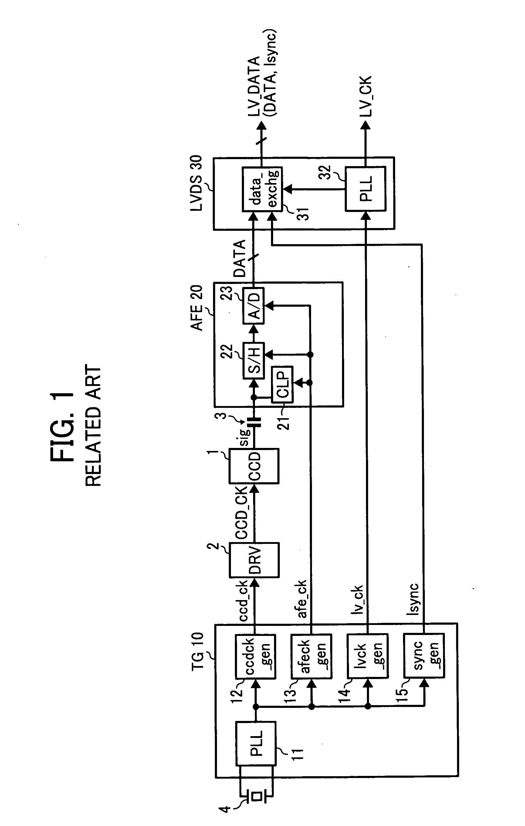
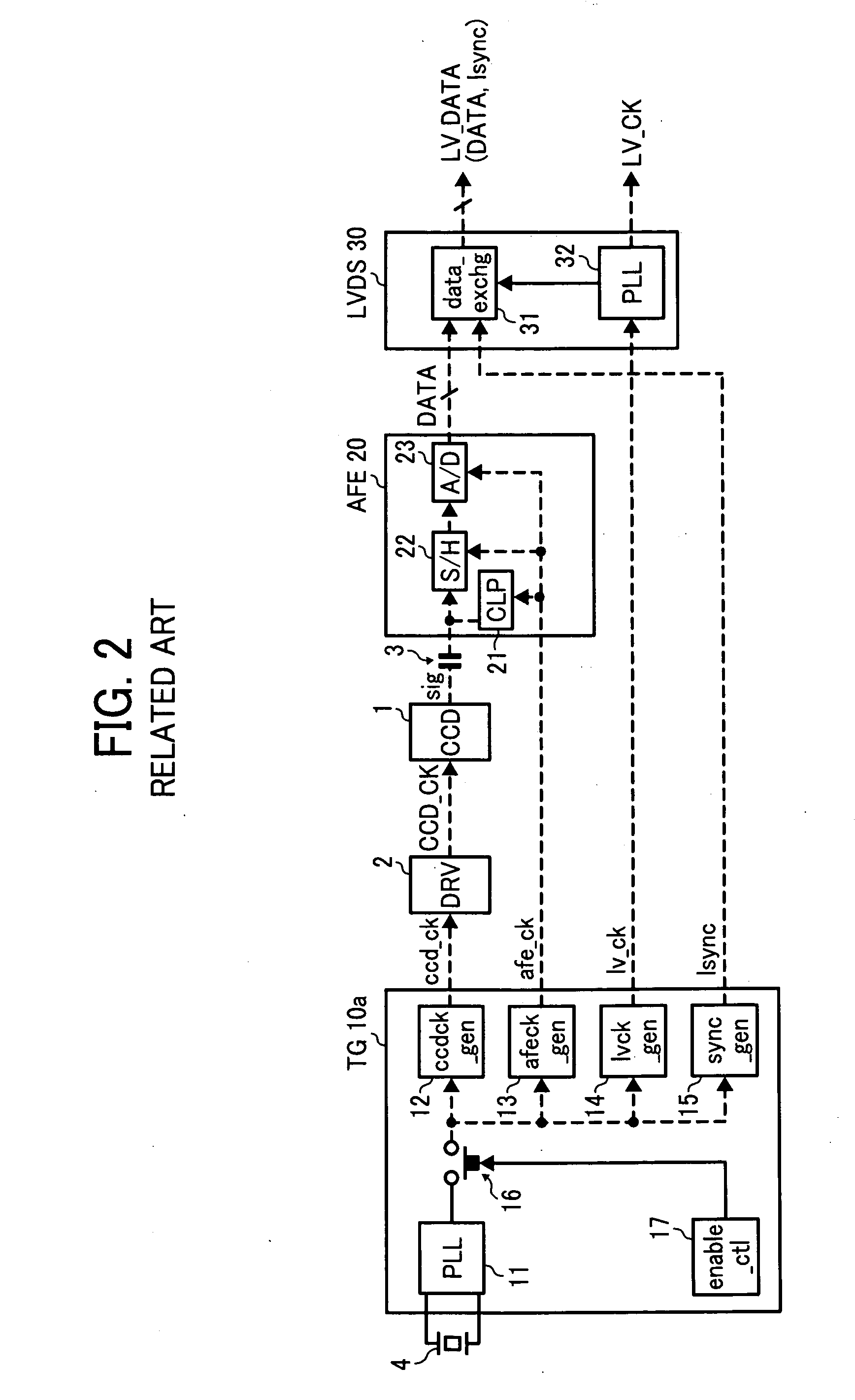
The present invention provides a signal processing circuit and an image scanner with a mode selector that can switch between two modes. In the first mode, the signal processing circuit operates normally, and in the second mode, a different control signal is supplied to the generator, transmission unit, and data transmitter. This allows for flexibility in the operation of the signal processing circuit and image scanner. A reference clock generator is constantly operating to generate a reference clock signal, which is used for the normal operation of the signal processing circuit and image scanner. A timing controller supplies control signals to the driving unit, analog processing unit, and data transmitter, ensuring the proper operation of the signal processing circuit and image scanner.

Problems solved by technology

Therefore, conventional image scanners continue to consume power during the standby mode unnecessarily, and overall power consumption is not reduced to the extent possible.
However, because the method of JP-4064161-B stops the supply of clock signal and / or synchronization signal to later-stage units disposed after the timing generator, when an instruction to return to the normal operating mode is received during the standby mode, a long time is required to return to the normal operating mode.

Method used


Image

  • Signal processing circuit, image scanner, and image forming apparatus
  • Signal processing circuit, image scanner, and image forming apparatus
  • Signal processing circuit, image scanner, and image forming apparatus

Examples


Embodiment Construction

[0032]A description is now given of exemplary embodiments of the present invention. It should be noted that although such terms as first, second, etc. may be used herein to describe various elements, components, regions, layers and / or sections, it should be understood that such elements, components, regions, layers and / or sections are not limited thereby because such terms are relative, that is, used only to distinguish one element, component, region, layer or section from another region, layer or section. Thus, for example, a first element, component, region, layer or section discussed below could be termed a second element, component, region, layer or section without departing from the teachings of the present invention.

[0033]In addition, it should be noted that the terminology used herein is for the purpose of describing particular embodiments only and is not intended to be limiting of the present invention. Thus, for example, as used herein, the singular forms “a”, “an” and “the...


PUM


Abstract

A signal processing circuit includes a generator, a transmission unit, a control unit, and a mode selector. The generator generates a process-required signal. The transmission unit transmits the process-required signal to a unit disposed after the transmission unit. The control unit supplies respective control signal to the generator and transmission unit. The control unit includes a reference clock generator constantly operated for generating a reference clock signal when the signal processing circuit is operated. The mode selector selects and shifts an operating mode of the signal processing circuit between a first mode and a second mode. In the first mode, the generator and transmission unit are supplied with respective normal control signal from the control unit for a normal operation. In the second mode, the generator is supplied with a control signal different from the normal control signal, and the transmission unit is supplied with the same normal control signal.

Description

CROSS-REFERENCE TO RELATED APPLICATION[0001]This application claims priority to Japanese Patent Application No. 2011-046294 filed on Mar. 3, 2011 in the Japan Patent Office, which is incorporated by reference herein in its entirety.BACKGROUND[0002]1. Technical Field[0003]The present invention relates to a signal processing circuit, unit such as a scanner; digital copier, a digital multi-functional apparatus, and a facsimile machine equipped with the signal processing circuit, an image scanner, and an image forming apparatus mounting the image scanning unit.[0004]2. Description of the Background Art[0005]Scanners are used to scan images from documents or the like. Specifically, light reflected from a document face-bearing an image thereon (hereinafter, “document image” or “document”) is received by an image sensor such as a charge coupled device (CCD), and converted to electrical signals to obtain a scanned document image. In general, a scanner uses a plurality of operating modes, su...

Claims


Application Information

Patent Timeline
Patent Type & Authority Applications(United States)
IPC IPC(8): G06K15/02
CPCH04N1/00896H04N1/00928H04N2201/04774H04N2201/04772H04N1/1013
Inventor NAKAZAWA, MASAMOTO
Owner RICOH KK
Learn More