
Signal generation method and signal generation apparatus

a signal generation and signal technology, applied in the direction of digital transmission, amplitude demodulation, transmission, etc., can solve the problems of reception quality degradation, reception quality degradation, and reception quality degradation

Inactive Publication Date: 2012-09-06
PANASONIC CORP
View PDF3 Cites 109 Cited by
  • Summary
  • Abstract
  • Description
  • Claims
  • Application Information

AI Technical Summary

Benefits of technology

[0034]According to the above structure, the present invention provides a signal generation scheme and signal generation apparatus that remedy degradation of reception quality in a LOS environment, thereby providing high-quality service to LOS users during broadcast or multicast communication.

Problems solved by technology

However, depending on the transmission system (e.g., a spatial multiplexing MIMO system), a problem occurs in that the reception quality deteriorates as the Rician factor increases (see Non-Patent Literature 3).
Thus, the problem of reception quality degradation upon stabilization of the propagation environment in the spatial multiplexing MIMO system, which does not occur in a conventional single-modulation signal system, is unique to the spatial multiplexing MIMO system.
When using a spatial multiplexing MIMO system having the above problem for broadcast or multicast communication, a situation may occur in which the received electric field strength is high at the reception device, but in which degradation in reception quality makes service reception difficult.
However, Non-Patent Literature 8 does not at all disclose a scheme for precoding in an environment in which feedback information cannot be acquired from the other party, such as in the above broadcast or multicast communication.
Non-Patent Literature 4 discloses using a unitary matrix as the precoding matrix, and switching the unitary matrix at random, but does not at all disclose a scheme applicable to degradation of reception quality in the above-described LOS environment.

Method used


Image

  • Signal generation method and signal generation apparatus
  • Signal generation method and signal generation apparatus
  • Signal generation method and signal generation apparatus

Examples


embodiment 1

[0111]The following describes, in detail, a transmission scheme, a transmission device, a reception scheme, and a reception device pertaining to the present Embodiment.

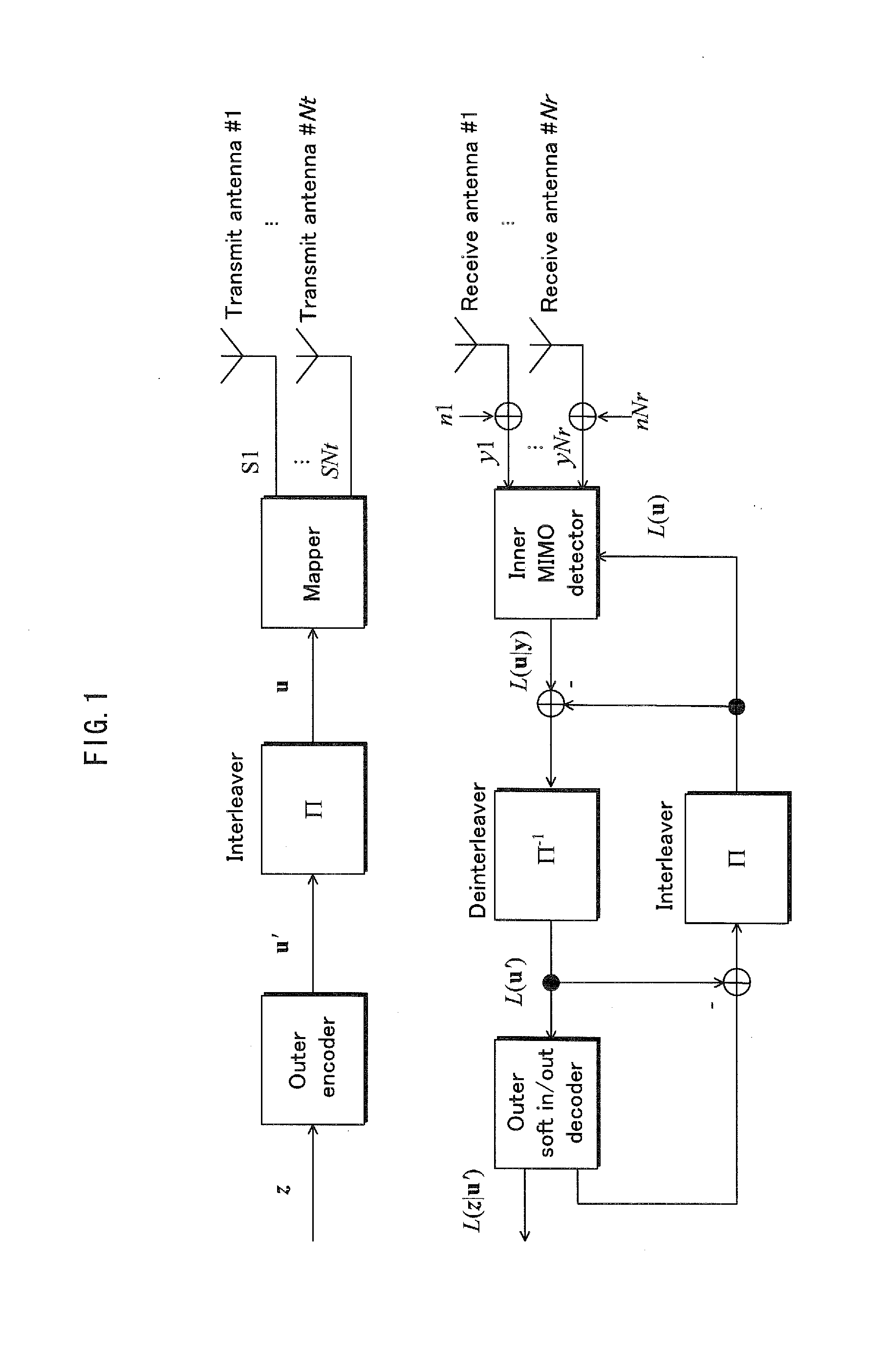
[0112]Before beginning the description proper, an outline of transmission schemes and decoding schemes in a conventional spatial multiplexing MIMO system is provided. FIG. 1 illustrates the structure of an Nt×Nr spatial multiplexing MIMO system. An information vector z is encoded and interleaved. The encoded bit vector u=(u1, . . . uNt) is obtained as the interleave output. Here, ui=(ui1, . . . uiM) (where M is the number of transmitted bits per symbol). For a transmit vector s=(s1, . . . SNt), a received signal si=map(ui) is found for transmit antenna #i. Normalizing the transmit energy, this is expressible as E{|si|2}=Es / Nt (where Es is the total energy per channel). The receive vector y=(y1, . . . yNr)T is expressed in Math. 1 (formula 1), below.

(formula1)y=(y1,…,yNr)T=HNtNrs+n[Math.1]

[0113]Here, HNtNr is the chann...

embodiment 2

[0262]In Embodiment 1, described above, phase changing is applied to a weighted (precoded with a fixed precoding matrix) signal z(t). The following Embodiments describe various phase changing schemes by which the effects of Embodiment 1 may be obtained.

[0263]In the above-described Embodiment, as shown in FIGS. 3 and 6, phase changer 317B is configured to perform a change of phase on only one of the signals output by the weighting unit 600.

[0264]However, phase changing may also be applied before precoding is performed by the weighting unit 600. In addition to the components illustrated in FIG. 6, the transmission device may also feature the weighting unit 600 before the phase changer 317B, as shown in FIG. 25.

[0265]In such circumstances, the following configuration is possible. The phase changer 317B performs a regular change of phase with respect to baseband signal s2(t), on which mapping has been performed according to a selected modulation scheme, and outputs s2′(t)=s2(t) y(t) (wh...

embodiment 3

[0303]Embodiments 1 and 2, described above, discuss regular changes of phase. Embodiment 3 describes a scheme of allowing the reception device to obtain good received signal quality for data, regardless of the reception device arrangement, by considering the location of the reception device with respect to the transmission device.

[0304]Embodiment 3 concerns the symbol arrangement within signals obtained through a change of phase.

[0305]FIG. 31 illustrates an example of frame configuration for a portion of the symbols within a signal in the time-frequency domain, given a transmission scheme where a regular change of phase is performed for a multi-carrier scheme such as OFDM.

[0306]First, an example is explained in which the change of phase is performed one of two baseband signals, precoded as explained in Embodiment 1 (see FIG. 6).

[0307](Although FIG. 6 illustrates a change of phase in the time domain, switching time t with carrier f in FIG. 6 corresponds to a change of phase in the fr...


PUM


Abstract

A transmission method simultaneously transmitting a first modulated signal and a second modulated signal at a common frequency performs precoding on both signals using a fixed precoding matrix and regularly changes the phase of at least one of the signals, thereby improving received data signal quality for a reception device.

Description

CROSS-REFERENCE TO RELATED APPLICATION[0001]This application is based on U.S. Patent Application No. 61 / 448,734 filed Mar. 3, 2011, the claims, description, drawings, and abstract of which are hereby incorporated by reference.BACKGROUND OF THE INVENTION[0002](1) Field of the Invention[0003]The present invention relates to a transmission device and a reception device for communication using multiple antennas.[0004](2) Description of the Related Art[0005]A MIMO (Multiple-Input, Multiple-Output) system is an example of a conventional communication system using multiple antennas. In multi-antenna communication, of which the MIMO system is typical, multiple transmission signals are each modulated, and each modulated signal is simultaneously transmitted from a different antenna in order to increase the transmission speed of the data.[0006]FIG. 23 illustrates a sample configuration of a transmission and reception device having two transmit antennas and two receive antennas, and using two t...

Claims


Application Information

Patent Timeline
IPC IPC(8): H04L27/06H04L27/04
CPCH04L5/0023H04L25/03171H04L25/03898H04L27/3444H04B7/0682H04L27/2601H04B7/0413H04B7/0669H04L1/005
Inventor MURAKAMI, YUTAKAKIMURA, TOMOHIROOUCHI, MIKIHIRO
Owner PANASONIC CORP
Features
  • Generate Ideas
  • Intellectual Property
  • Life Sciences
  • Materials
  • Tech Scout
  • Unparalleled Data Quality
  • Higher Quality Content
  • 60% Fewer Hallucinations
Learn More