
Display Device

a display device and display technology, applied in the field of display devices, can solve the problems of limiting the type of photos or artistic media which may be displayed in prior art devices, and affecting the display effect of the display device,

Inactive Publication Date: 2012-09-13
BAUER TIM
View PDF4 Cites 4 Cited by
  • Summary
  • Abstract
  • Description
  • Claims
  • Application Information

AI Technical Summary

Benefits of technology

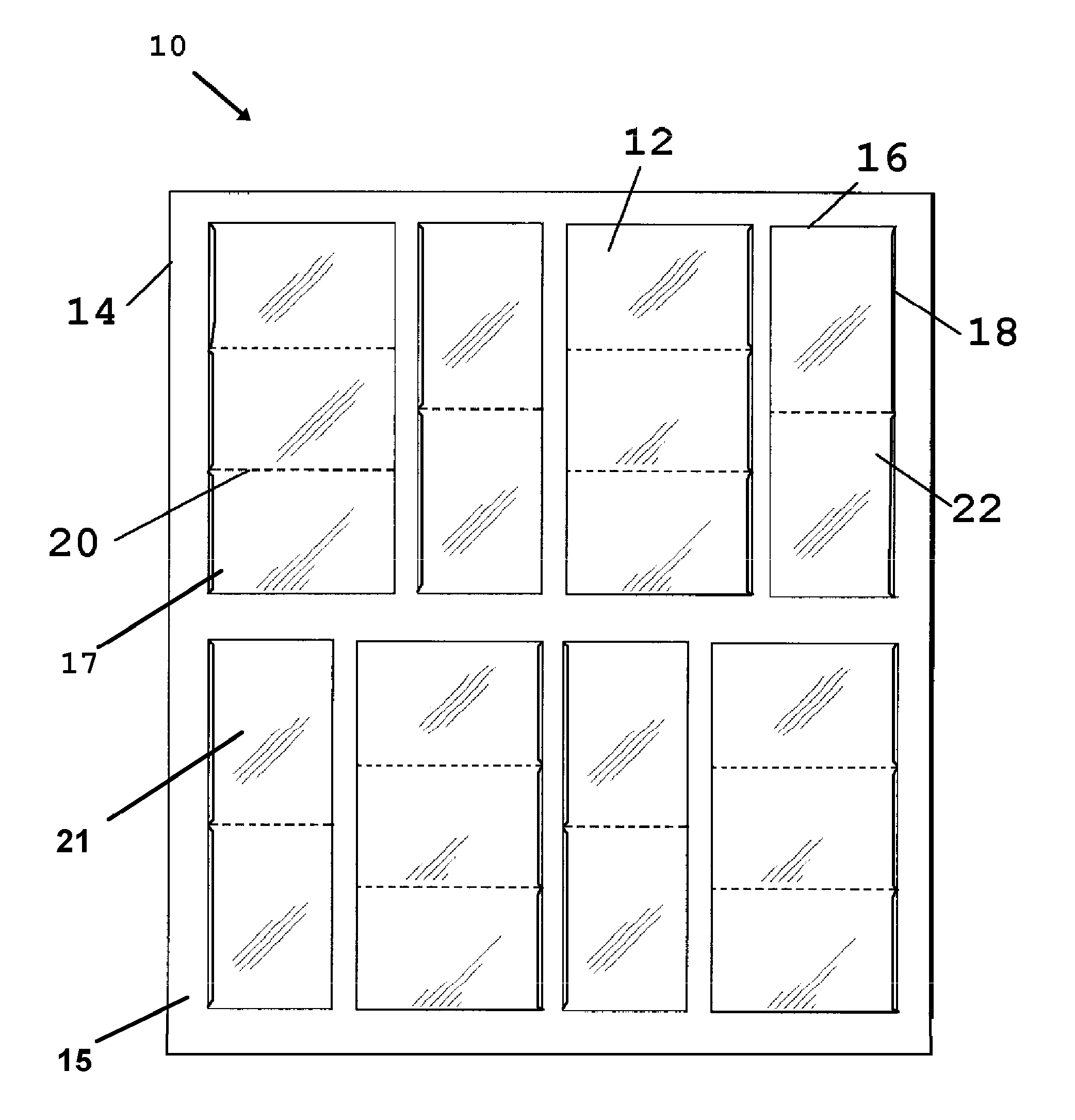
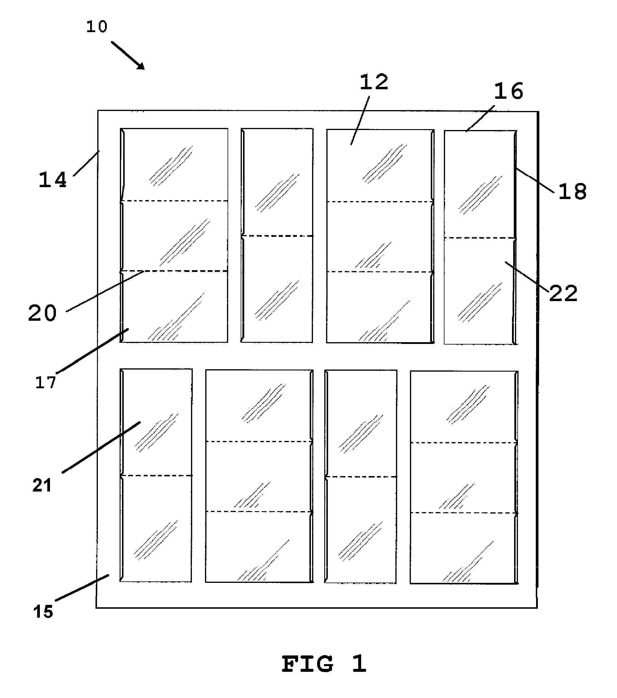
[0009]The device herein disclosed and described provides a means to display photographs and other planar or flat media through the provision of a device having at least one sidewall formed to provide a transparent panel or plurality of panels engaged on a back support panel. Each formed transparent panel provides individual discrete receiving cavities or pockets in which photos or artwork or planar media is insertable through slot openings oriented along either the transverse or longitudinal direction of the panel. The openings communicating with a display cavity behind the transparent panel will thereby accommodate and protect the surfaces of photographs, artwork, or other such media to be displayed by a user.
[0010]The formed discrete pockets forming the receiving cavities can be easily lengthened or shortened by the user to allow for the accommodation of varying dimensions and shapes of photos and other media for engagement therein. Resizing is provided through the employment of removably engageable adhesives or other such removable engagement means which engage the transparent wall to an underlying rear surface to define the perimeter edges which define the pocket or display cavity for the photos or artwork. For example, in the disclosed device, two pockets side by side which each share an abutting edge on one side of their respective defined storage cavities may be adjusted for size by disengaging the common edge and either creating two new pockets of differing dimensions, creating a single pocket of a new dimension. Additionally, the planar back support panel to which the transparent sidewall is engaged, may be transparent as well if it is desired to display both sides of the displayed media. The planar back is best formed of a polymeric material such as polyethylene or polypropylene as is the front transparent wall.

Problems solved by technology

However, when employing conventional frames for such an endeavor, the task of assembling the various photos and artwork into a single displayed component and surrounding them with frames, and accommodating different sized photos, is at best a cumbersome task and may even involve framing and at least matting of each individual photo or item to be grouped in the display.
As a result, instead of being limited to sending film to a lab, and settling upon very few sizes of available photo prints, digital photographers may use software to resize and reformat photos, and print them in virtually an infinite number of dimensions.
Consequently, finding frames and photo display holders or matting to accommodate a plurality of sizes of printed digital photos of infinite size variance, has become a major problem.
However, as mentioned, the pockets or framed display components are of fixed dimensions and only allow for insertion of media of the same or smaller dimension, such as photographs printed to standard photograph dimensions or baseball cards in standard card sizes.
This restricts the type of photos or artistic media which may be displayed in prior art devices and is undesirable for large photographs, custom formatted and printed photographs, and artistic media desired for display which is of nonconventional sizes such as panoramic photographs.

Method used


Image

  • Display Device
  • Display Device
  • Display Device

Examples


Embodiment Construction

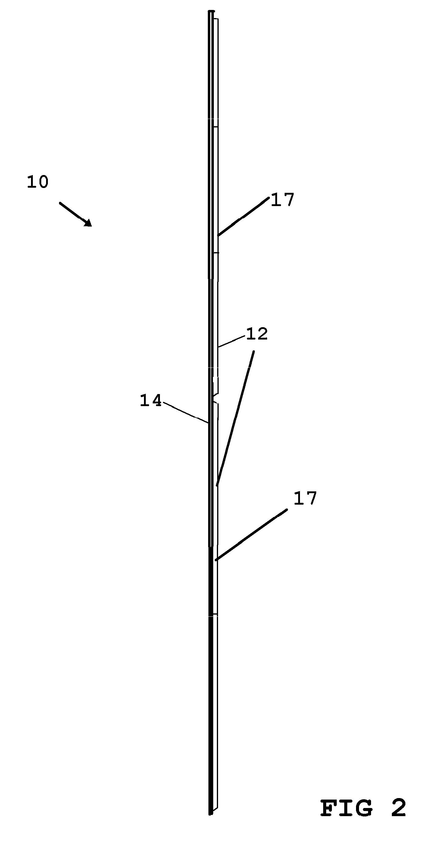
[0022]Now referring to drawings in FIGS. 1-3, wherein similar components are identified by like reference numerals, there is seen in FIG. 1 a depiction typical of a preferred embodiment of the display device 10. One, or as depicted, a plurality of thin transparent plastic panels 12 formed of polymeric material, are engaged about at least two perimeter edges 16, to a support panel 14. The support panel 14 may be cardboard, posterboard, or preferably lightweight polymeric material of the like.

[0023]Polymeric material such as polyethylene or polypropolone sheet for example is a preferred material as it allows a rolling of the support panel 14 with the plastic panel 12 engaged, to provide a means to transport the device 10 with photos or art in the cavities 22 and prevent creasing or wrinkling of the contained photo or artwork in the cavity 22. The support panel 14 may also be substantially transparent in nature, so as to allow viewing of the rear of photos, art, or other planar media c...


PUM


Abstract

A user-configurable photo and planar media display device is provided with adjustable pockets to hold the photos, art, or media. A transparent front wall is removably engageable to a support surface to allow user configuration and redimensioning of the formed pockets, to match their photos or media for insertion therein.

Description

[0001]This application claims priority to U.S. Provisional Application Ser. No. 61 / 450,091 filed on Mar. 7, 2011, and is incorporated herein in its entirety by this reference.BACKGROUND OF THE INVENTION[0002]1. Field of the Invention[0003]The present invention relates to display devices for photographs, printed images, postcards, and other media which a user wishes to protect, transport, and display. More particularly, it relates to a windowed display assembly with receiving pockets having transparent walls which protect the underlying printed media and which can be adjusted to different sizes and dimensions to accommodate a plurality of sizes of planar media.[0004]2. Prior Art[0005]The display of photographs and planar media such as photographs, postcards and artwork is conventionally positioned in a singular framed component such as a picture frame. Such frames may or may not have a transparent covering over the displayed media. Frequently, it is desirable to display photographs i...

Claims


Application Information

Patent Timeline
Patent Type & Authority Applications(United States)
IPC IPC(8): A47G1/08
CPCG09F1/10A47G1/065
Inventor BAUER, TIM
Owner BAUER TIM
Learn More