Operation Switch

a technology of operation switch and switch body, which is applied in the direction of snap-action arrangement, contact mechanism, contact, etc., can solve the problems of increasing manufacturing and assembly cost, increasing etc., and achieves the effect of facilitating bending deformation, and reducing the number of components

Active Publication Date: 2012-09-13
IDEC CORPORATION
View PDF6 Cites 8 Cited by
  • Summary
  • Abstract
  • Description
  • Claims
  • Application Information

AI Technical Summary

Benefits of technology

[0023]In contrast, in the event that radius of curvature of the arc-shaped portion of the second leaf spring is greater than radius of curvature of the arc-shaped portion of the first leaf spring, bending rigidity of the arc-shaped portion of the second leaf spring is smaller than bending rigidity of the arc-shaped portion of the first leaf spring and the arc-shaped portion of the second leaf spring is thus easier to be bending-deformed than the arc-shaped portion of the first leaf spring. In this case, when the contacting portion in the switch case has come into contact with the other end of the second leaf spring, the second leaf spring is easier to deform than the first leaf spring. Thereby, opening timing of the contacts can be adjusted.
[0024]As above-mentioned, according to the operation switch of the present invention, since the first and second contacts are provided in the switch case at a portion of a leaf spring as a contact-opening-biasing means, there is no need to provide a spring as an opening-biasing means discretely from a contact and also the leaf spring in itself comes to function as a conductive plate with a contact. Thereby, the number components can be reduced and a manufacturing and assembly cost can be decreased.

Problems solved by technology

However, in the abovementioned structure of prior art, there needs to be provided a spring discretely from the contacts that biases the movable contact away from the fixed contact, and as a result it is disadvantageous that the number of components increases and thus a manufacturing and assembly cost increases.

Method used


Image

  • Operation Switch
  • Operation Switch
  • Operation Switch

Examples


Embodiment Construction

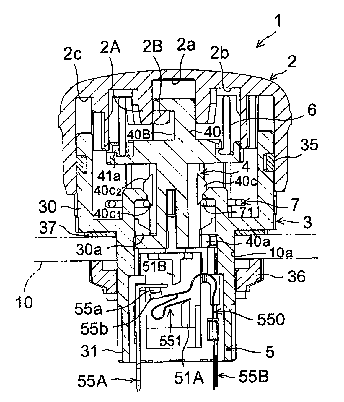
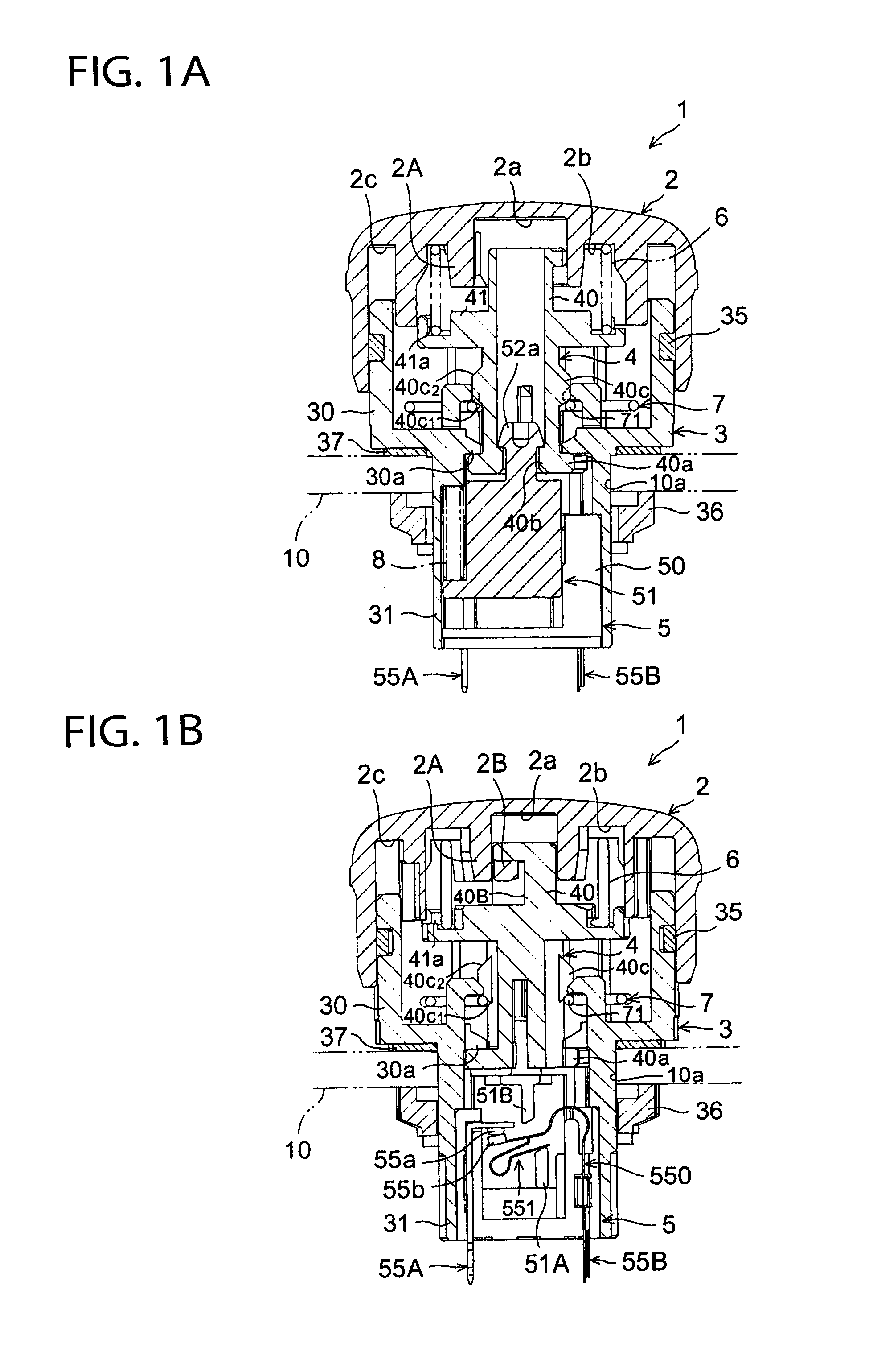
[0043]Embodiments of the present invention will be hereinafter described in accordance with the appended drawings.

[0044]FIGS. 1 to 9 illustrate a push button switch for emergency stop as an operation switch according to an embodiment of the present invention.

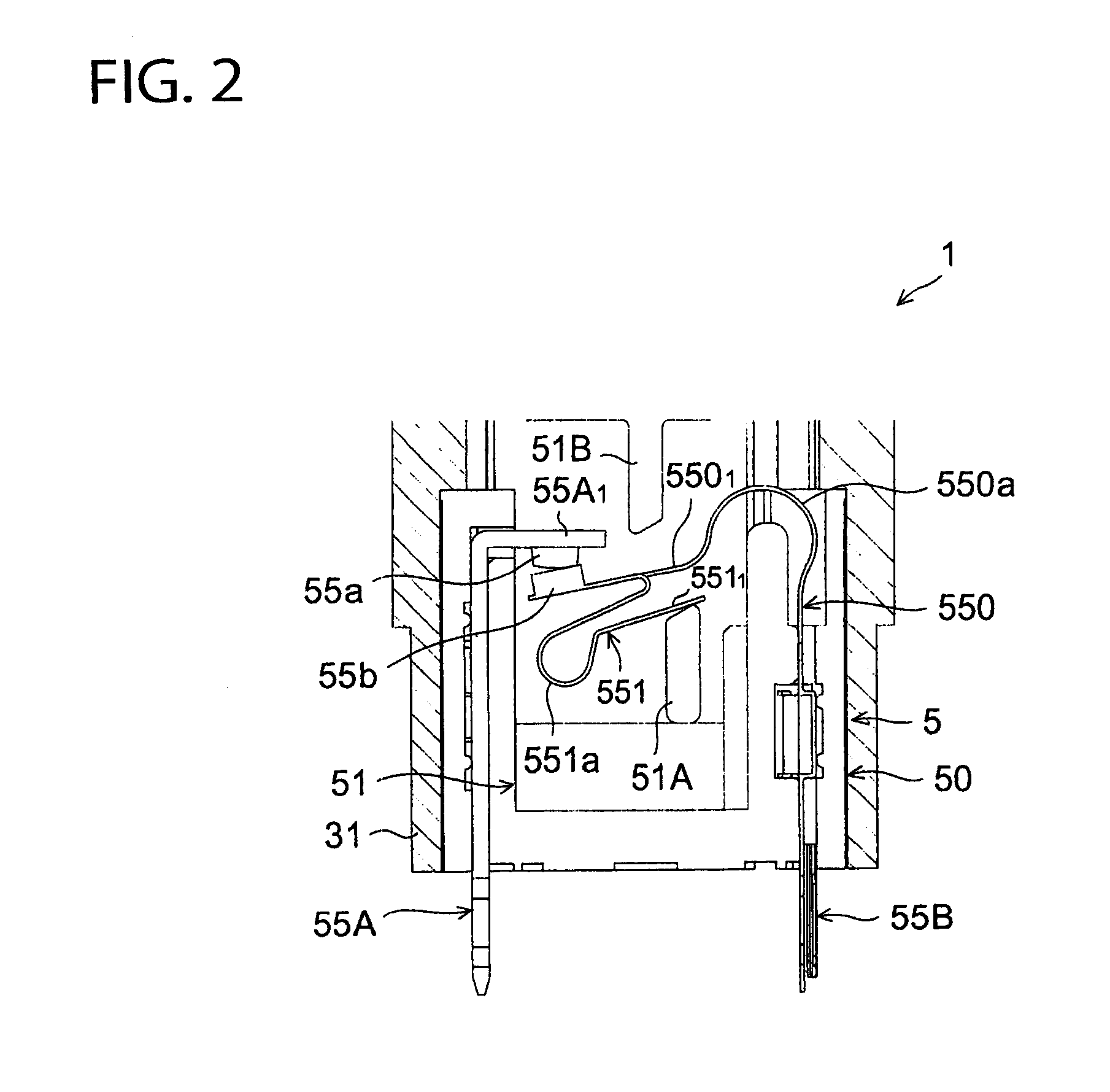
[0045]As shown in FIGS. 1A, 1B and 8, a push button switch 1 includes a push button 2 as an operating element for an operator to operate, a switch case 3 to hold the push button 2, an operating spindle 4 held in the switch case 3 and adapted to enter the inside of the switch case 3 in association with a press of the push button 2, and a contact unit 5 held in the switch case 3 and engaged with a distal end of the operating spindle 4.

[0046]The push button 2 is a cuplike member having a central hole 2a formed therein and annular grooves 2b, 2c formed around the central hole 2a. Between the central hole 2a and the annular grooves 2b, an annular protrusion 2A is formed. The central hole 2a has an engaging projection 2B at a part the...


PUM


Abstract

A push button switch 1 is so constructed as to disengage the movable contacts 55b, 56b from the fixed contacts 55a, 56a through operation of the push button 2 held in the switch case 3. A first leaf spring 550 is provided in the switch case 3 to act as an opening-biasing means to bias the movable contacts 55b, 56b away from the fixed contacts 55a, 56a. The movable contact 55b is disposed at an end of the first leaf spring 550 and adapted to engage with and disengage from the fixed contact 55a. The first leaf spring 550 is adapted to be at a position where the movable contact 55b is open relative to and disengaged from the fixed contact 55a at zero displacement of the first leaf spring 550.

Description

TECHNICAL FIELD[0001]The present invention relates generally to an operation switch such as a push button switch and the like, and more particularly to improvements in operation switches for decreasing manufacturing and assembly costs by reducing the number of components thereof.BACKGROUND ART[0002]Generally, in a control panel for mechanical equipment such as machine tools and the like, a push-button-type emergency stop switch is provided to emergency-stop mechanical equipment at the time of abnormal circumstances. In such a push-button-type switch, for example, Japanese patent application laying-open publication No. 2003-303527 (hereinafter referred to JP '527) discloses a switch equipped with a “safety-potentials® structure”, which is a registered trademark of IDEC Corporation, such that contacts of the switch will not return to a contact state in the event that the switch is damaged.[0003]As shown in FIGS. 1 and 2 of JP '527, the button housing 9 receiving the push button 5 incl...

Claims


Application Information

Patent Timeline
Patent Type & Authority Applications(United States)
IPC IPC(8): H01H1/26
CPCH01H1/26H01H3/022H01H5/18H01H13/62H01H13/20H01H13/36H01H13/02
Inventor KAWAGUCHI, KENICHITANIGUCHI, MASAZUMIMATSUMOTO, ATSUSHIFUJIMOTO, MASASHIONISHI, YASUO
Owner IDEC CORPORATION
Why Eureka
Try Eureka