Novel tubeless pneumatic tire without sidewall supporting

A sidewall support and pneumatic tire technology, applied in the direction of no separate air cushion, tire parts, transportation and packaging, etc., can solve the problems of affecting the dynamic balance of the tire, increasing the rolling resistance of the wheel, and increasing the difficulty of the rim, so as to reduce the The effect of small unbalanced force, increased driving speed, and reduced probability of tripping

Pending Publication Date: 2019-05-10
卫向坡
View PDF0 Cites 2 Cited by
  • Summary
  • Abstract
  • Description
  • Claims
  • Application Information

AI Technical Summary

Problems solved by technology

[0006] In the prior art, self-supporting run-flat tires with thicker sidewalls can support the weight of the car body through the sidewall of the tire and drive at a certain speed for a period of time when the tire pressure is 0; but this technology has certain defects : 1. After the tire sidewall is thickened and strengthened, the tire becomes harder, the comfort of the vehicle is reduced, and there are higher requirements for the chassis and shock absorption. At the same time, the tire is easy to damage the wheel hub after being impacted; 2. The installation is difficult, and special tire removal is required Equipment; 3. Heavy tires, poor handling, high fuel consumption, high cost of use, and not environmentally friendly; 4. Expensive tires, high installation costs; 5. The side wall support is limited, and heavy vehicles such as buses and trucks cannot be used
[0007] In the prior art, an annular support belt is installed in the hub wheel groove to seal the wheel hub wheel groove, preventing the tire lip from sliding into the wheel hub wheel groove when the tire without sidewall support is flattened at 0 air pressure, and avoiding traffic accidents. However, this This technology has certain defects: 1. The installation process is cumbersome and complicated, and the tire disassembly is inconvenient, and special disassembly tools are required; 2. The wheels are heavy, which affects fuel consumption; 3. The cost is high; 4. After the tire is flattened at zero air pressure Although the tire cannot slip off the wheel groove, it is easy to slip off the bead seat under the action of the tire's lateral force. After the tire slips, the lateral force of the tire will decrease, and it will be difficult for the driver to accurately control the direction; 5. After being flattened at 0 air pressure, the contact positions of the inner surface of the tire rub against each other. The rubber layer of the inner layer of the tire is a rubber inner layer, which mainly has requirements for airtight performance. There is no high requirement for wear resistance and lubrication. The friction coefficient of the inner surface of the tire 6. After the tire is flattened at 0 air pressure, the rolling resistance of the wheel will increase, which will lead to unbalanced force on the left and right wheels and poor handling; 7. It is easy to affect the dynamic balance of the tire after installation, and it is easy to cause safety hazards such as loose installation during use
The tire and the rim are integrated, which increases the difficulty of using the rim repeatedly, and it will be very troublesome if the tire is punctured
At the same time, after the tire is flattened at 0 air pressure, the inner surfaces of the tires rub against each other. The rubber layer of the inner layer of the tire is a rubber airtight layer, which mainly has requirements for airtight performance, and has no requirements for wear resistance and lubrication. Friction heats up and wears out, resulting in slow running speed and short driving distance of 0-pressure tires; after the 0-pressure tires are flattened, the rolling resistance of the wheels becomes larger, which will cause unbalanced force on the left and right wheels

Method used


Image

  • Novel tubeless pneumatic tire without sidewall supporting
  • Novel tubeless pneumatic tire without sidewall supporting
  • Novel tubeless pneumatic tire without sidewall supporting

Examples


Embodiment 1

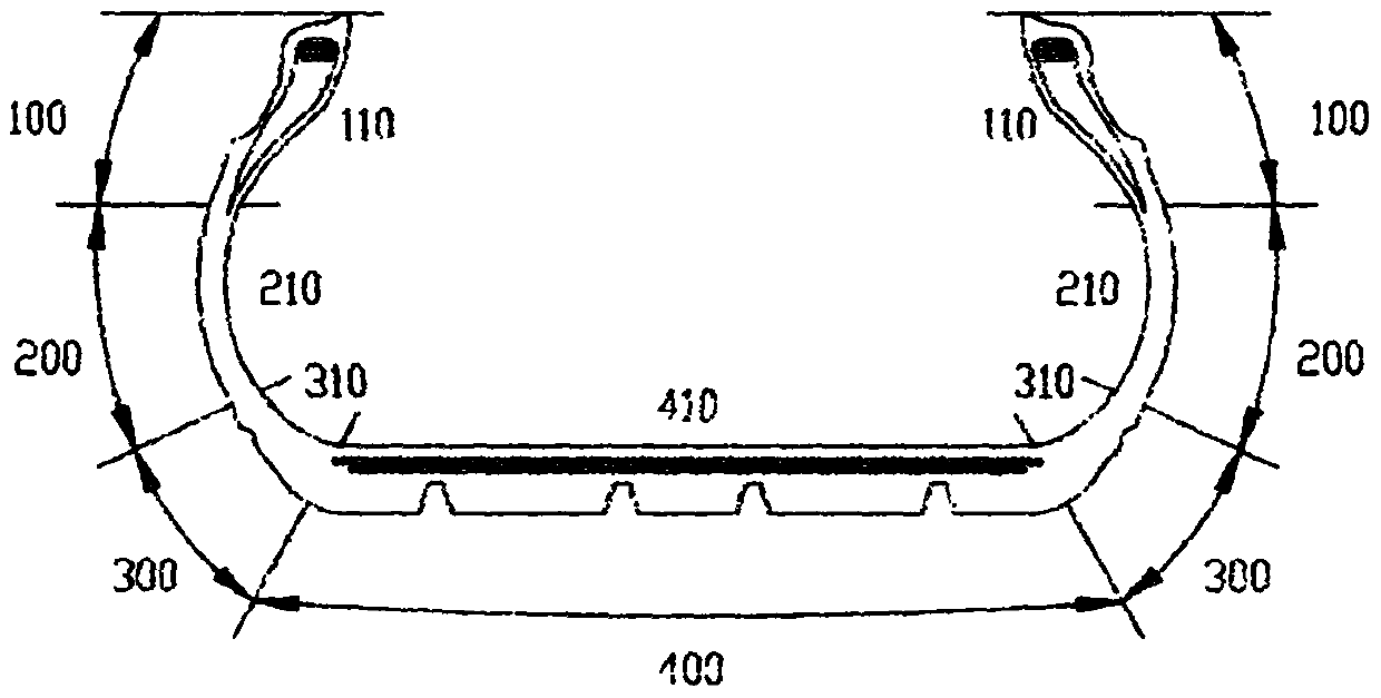
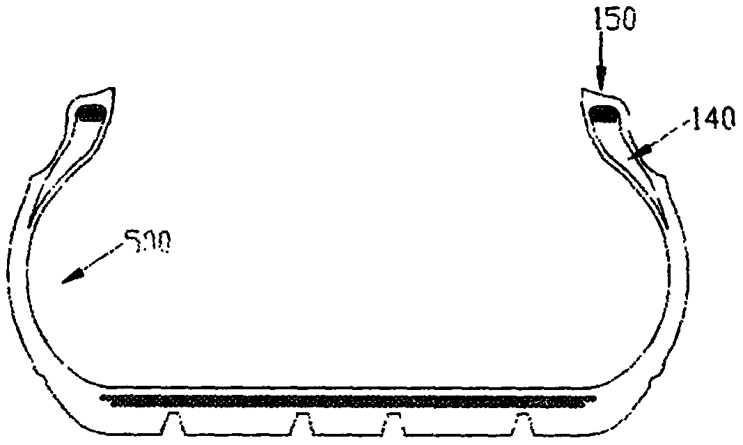
[0066] Reference attachment Figure 1-Figure 3 , Figure 5 , Image 6 , Figure 5 , Image 6 The tire is the left front tire, the vehicle is a family car, and the camber angle of the wheel under normal tire pressure is 0; the tire is a tire with a small aspect ratio, and the sidewall 200 has a small height, and the inner surface of the bead on both sides of the tire is 110, or two A wear-resistant lubricating layer is provided on the inner surface 110 of the side bead part, the inner surface 210 of the sidewall, and the inner surface of the shoulder 310. The wear-resistant lubricating layer is silicone grease + nylon cloth + rubber layer. The rubber layer of the rubber nylon cloth is attached to the inner surface of the tire inner layer 500, and then molded on the tire building drum, and finally vulcanized and molded. After the tire is vulcanized and molded, the nylon cloth is coated with silicone grease; silicone lubrication Grease + nylon cloth has good lubricity and wear resi...

Embodiment 2

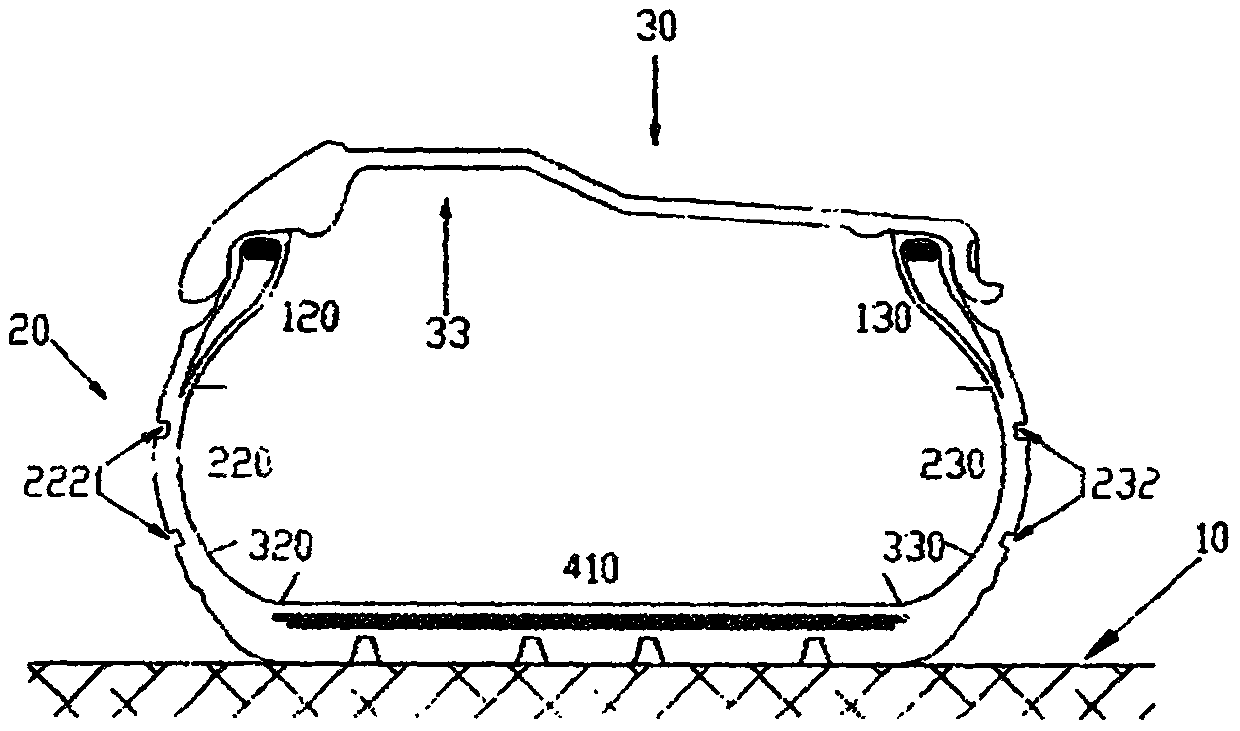
[0078] Reference attachment Figure 1-Figure 3 , Figure 5 , Image 6 , Figure 5 , Image 6 The tire is the left front tire. Compared with Example 1, this embodiment is only different from the tire. The differences are: 1. The height of the sidewall 200 is different from that of Example 1, and the height of the sidewall 200 is higher than that of the sidewall 200 described in Example 1. The height is slightly higher, and the cross-sectional height of the tire at standard pressure is higher than that of Example 1. 2. On the inner surface 120 of the vehicle outer bead portion, or on the inner surface 120 of the vehicle outer bead portion, the vehicle outer sidewall inner surface 220, and the vehicle Silicone grease+nylon cloth+rubber layer is set on the inner surface 320 of the outer shoulder. The thickness of the silicone grease+nylon cloth+rubber layer is 1mm; the inner surface of the bead part 130, the inner surface of the sidewall 230, and the inner side of the vehicle The in...

Embodiment 3

[0084] Reference attachment Figure 1-Figure 3 , Figure 5 , Image 6 , Figure 5 , Image 6 The tire is the left front tire. Compared with Example 2, only the tire is different in this embodiment. The difference is: 1. The height of the sidewall 200 is higher than the height of the sidewall 200 described in Example 2. The cross-section of the tire at standard pressure The height is higher than that of Example 2; 2. Set silicone grease on the inner surface 120 of the vehicle outer bead part, or on the inner surface of the vehicle outer bead part 120, the vehicle outer sidewall inner surface 220, and the vehicle outer shoulder inner surface 320. The thickness of nylon cloth + rubber layer, silicone grease + nylon cloth + rubber layer is 1mm. The inner surface 130 of the bead portion inside the vehicle, the inner surface 230 of the sidewall inside the vehicle, and the inner surface 330 of the inner shoulder of the vehicle are not arranged as inner surfaces of the inner liner.

[00...


PUM

PropertyMeasurementUnit
thicknessaaaaaaaaaa

Abstract

The invention discloses a novel tubeless pneumatic tire without sidewall supporting. Part of the inner surfaces of beads of the tire, and / or the inner surfaces of sidewalls, and / or the inner surfacesof shoulders are provided with wear-resistant layers and / or wear-resistant lubricating layers. After the zero-pressure tire is flattened, two inner surfaces of the inner layer of the tire are in contact with each other; the wear-resistant layers are arranged at the contact position so as to improve the wear resistance and increase the driving mileage and driving speed of the tire; the wear-resistant lubricating layers are arranged at the contact position so as to reduce the friction coefficient of a contact surface, reduce the friction and reduce the risk of detachment of the tire; the reduction of the friction can improve the wear resistance and increase the driving mileage of the tire; the reduction of the friction is capable of reducing the rolling resistance of the tire, reducing the situation of unbalanced stress on wheels on two sides, and improving the handling of a vehicle; and in the contact position, when a tread slides towards one of the shoulders, two steeply-sloped side surfaces of a protrusion structure on the side adjacent to the corresponding shoulder are in contact with each other so as to prevent the tread from sliding towards the corresponding shoulder and improve the handling of the vehicle.

Description

Technical field [0001] The invention relates to a new type of pneumatic tire with no inner tube and no sidewall support, which belongs to the technical field of motor vehicle tires. Background technique [0002] Once the tire bursts, the tire without sidewall support is squashed, the inner surface of the tire inner layer touches, the car body tilts, and the camber angle of the wheel will change. Wheel camber: refers to the angle between the plane of the wheel and the longitudinal vertical plane after the wheel is installed; when the tire is in the shape of "eight", it is called negative camber, and when it is in the shape of "V", it is called positive camber. reference Picture 11 , Picture 11 The wheel in the middle is the right wheel of the vehicle. [0003] Once a tire bursts, the tire is at zero air pressure, and the tire without sidewall support is squashed. The rolling resistance of the tire with a flat tire will increase significantly. The force on the left and right sides w...

Claims


Application Information

Patent Timeline
Patent Type & Authority Applications(China)
IPC IPC(8): B60C17/10
CPCB60C17/10B60C17/00B60C17/08B60C5/14B60C17/103B60C17/106B60C5/12B60C2017/0081
Inventor 卫向坡
Owner 卫向坡
Why Eureka
Try Eureka