Vehicle hood panel

a technology for hood panels and vehicles, applied in the direction of vehicle components, superstructure connections, superstructure subunits, etc., can solve the problems of hood panel being easily bending deformed, etc., to achieve easy bending deformation, easy propagation, and pedestrian protection high

Active Publication Date: 2016-06-28
KOBE STEEL LTD
View PDF48 Cites 2 Cited by
  • Summary
  • Abstract
  • Description
  • Claims
  • Application Information

AI Technical Summary

Benefits of technology

[0051]In the vehicle hood panel according to the present invention (the first invention), the inner panel has the joining point surface joined to the outer panel by mastic, and the beads of concave cross section are extended downwardly from the joining point surface and extended in the vehicle right-left direction to be surrounded by the joining point surface, and in at least one of the vertical walls of each bead on the vehicle front and rear sides, the upper edge thereof is curved so that in plan view, the radius of curvature at the center portion in the vehicle right-left direction is smaller than the radius of curvature at the end in the vehicle right-left direction. That is, since the bead is extended in the vehicle right-left direction, at front collision of vehicles, the hood panel is easily bending-deformed, and at pedestrian collision, the curved portions at the center portion of the vertical walls in which the radius of curvature is small in plan view act as reinforcing ribs to restrain the side walls from being spread-deformed. With this, according to the present invention, while the bending deformation performance at front collision of vehicles can be ensured, the pedestrian protection performance of the hood panel can be prevented from being non-uniform in the vehicle right-left direction. The pedestrian protection performance can be high without depending on the collision position of the head of a pedestrian. In particular, when the inner panel has the bead in which the bottom is curved to be convex to the vehicle front or rear side, the collision energy is easily propagated in the vehicle front-rear direction. With this, the amount of energy absorption in the initial stage of collision is increased to enhance the pedestrian protection performance.
[0052]In the vehicle hood panel according to the present invention (the second invention), the inner panel has the joining point surface joined to the outer panel by mastic, and the beads of concave cross section are extended downwardly from the joining point surface and extended in the vehicle right-left direction to be surrounded by the joining point surface, the depth of the bottom from the joining point surface of the bead at the center portion in the vehicle front-rear direction is greater than the depth of the bottom from the joining point surface of the bead at the end in the vehicle front-rear direction. Alternatively, the bottom of the bead at the center portion in the vehicle front-rear direction is deeper at the center portion than at the end in the vehicle right-left direction. Therefore, as compared with when the head of a pedestrian collides with the vicinity of the end of the hood panel, when the head of the pedestrian collides with the vicinity of the center of the hood panel, the timing at which the inner panel is subjected to secondary collision with the incorporated components inside the hood comes early, so that the deformation acceleration after primary collision can be restrained from being lowered. With this, at the center portion of the hood panel in the vehicle front-rear direction, the amount of energy absorption in the initial stage of collision is increased to reduce the peak value of the second wave of acceleration at secondary collision, thereby improving the pedestrian protection performance. On the other hand, at the end in the vehicle front-rear direction and in the vehicle right-left direction, by the rigidity of the vertical wall, the pedestrian protection performance can be stable. According to the present invention, the pedestrian protection performance can be high without depending on the collision position of the head of the pedestrian.
[0053]According to the present invention (the third invention), the mastic joining portion of the inner panel to the outer panel is provided near the striker at the vehicle front end. The dent resistance is easily ensured without setting the dent reinforcing member. In addition, the side of the bead that stretches to the mastic joining portion is present on the outer side of the striker in the vehicle width direction, thereby surrounding the striker. Therefore, the dent resistance and rigidity of the panel in the portion immediately above the striker can be easily ensured. Further, in the present invention, when the head of a pedestrian collides with the vicinity of the lock reinforcing member, the stress is easily propagated in the vehicle front-rear direction through the mastic joining surface. The deformation area in the initial stage of collision can be increased, and according to increase of the inertia mass, the primary peak of acceleration can be improved. With this, the amount of energy absorption in the first half of collision can be increased. The HIC value can thus be reduced to improve the pedestrian protection performance.

Problems solved by technology

However, when considering that the components necessary for the automobile are disposed below the hood in the limited space, it is often difficult to sufficiently ensure the gap between the hood panel and the incorporated components.
In addition, in many cases, a child pedestrian collides with the front of the hood panel, and an adult pedestrian collides with the rear of the hood panel.
The hood panel is thus easily bending-deformed at front collision.
However, since the above structure uses two reinforcing members, the number of components is increased to make the cost higher.
At pedestrian head collision, the leg connecting the joining surface to the outer panel and the lower surface of the inner panel to which the striker is joined is difficult to be bent.
However, in such a structure, the number of components is increased to make the cost higher.

Method used


Image

  • Vehicle hood panel
  • Vehicle hood panel
  • Vehicle hood panel

Examples


first embodiment

[0113](First Embodiment)

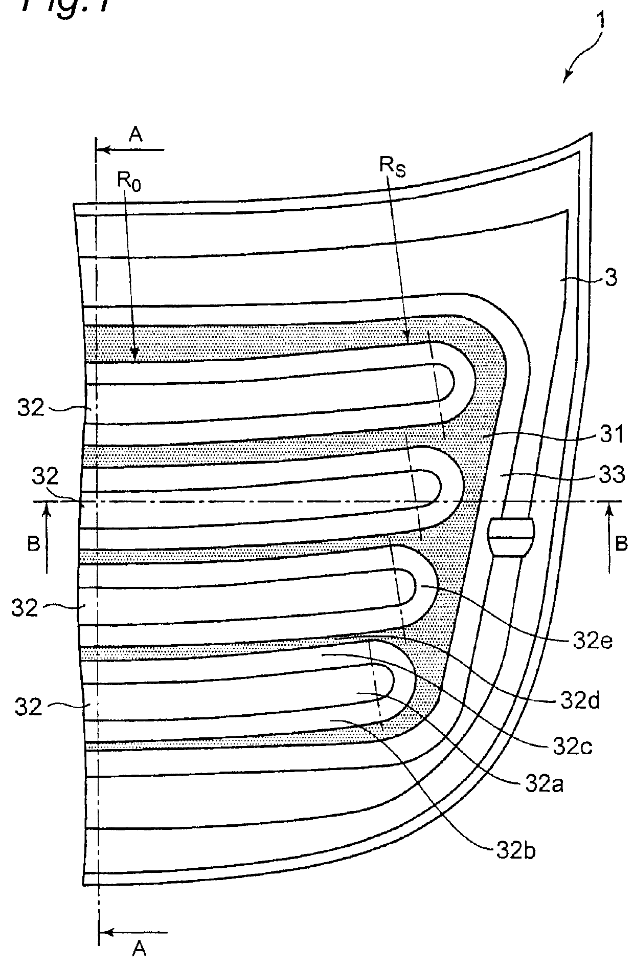
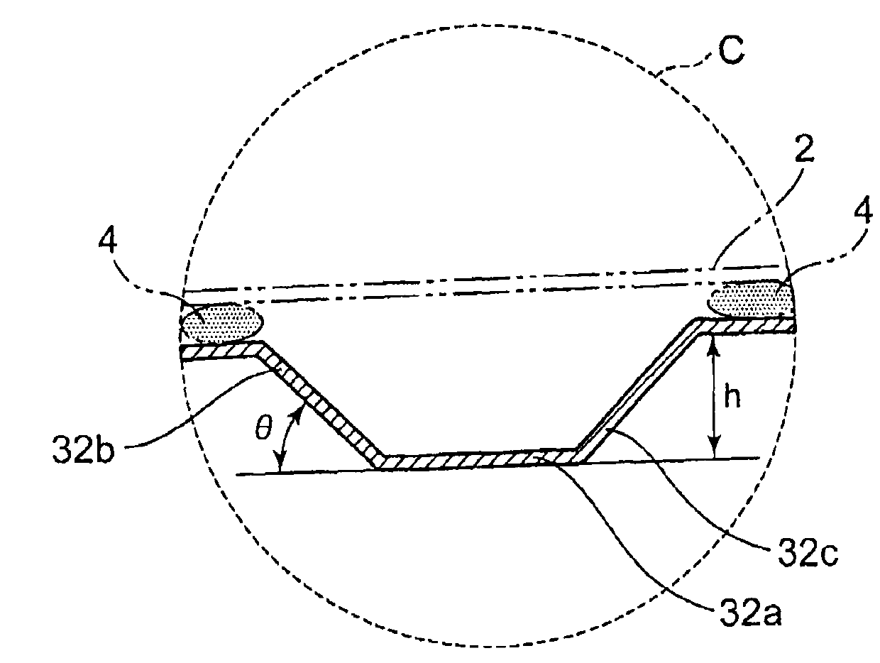
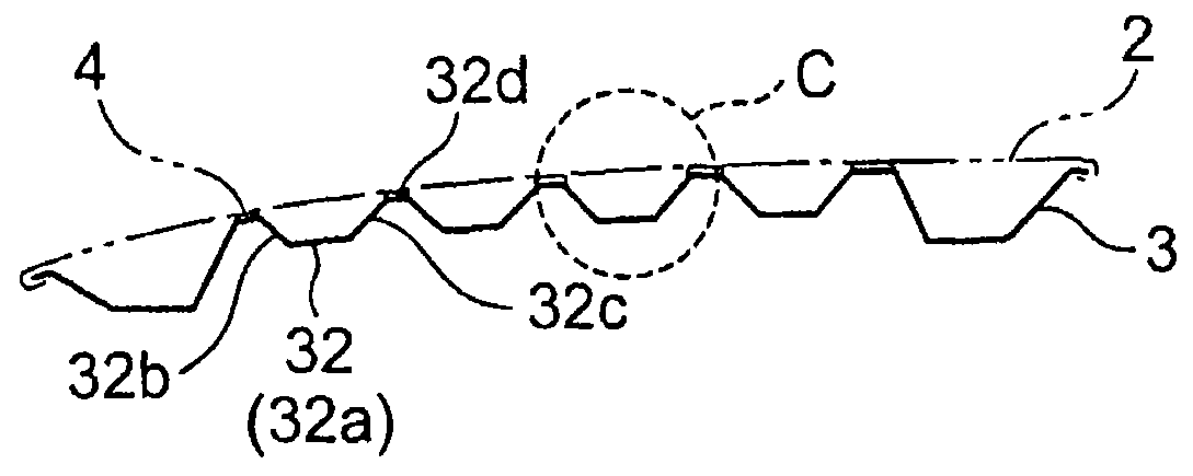
[0114]The structure of a vehicle hood panel according to a first embodiment of the present invention will be described. FIG. 1 is a plan view showing the vehicle hood panel according to the first embodiment of the present invention. FIG. 2(a) is a cross-sectional view taken along line A-A in FIG. 1. FIG. 2(b) is a cross-sectional view taken along line B-B in FIG. 1. FIG. 2(c) is an enlarged view of portion C in FIG. 2(a). Like the conventional vehicle hood panel 10 shown in FIG. 28(a), as shown in FIG. 1, a vehicle hood panel 1 according to this embodiment has an inner panel 3, and an outer panel 2. For instance, the outer edge of the inner panel 3 is joined to the outer edge of the outer panel 2 by hemming. The inner panel 3 and the outer panel 2 are formed of a metal plate of e.g., iron, aluminum, or an aluminum alloy, and have a plate thickness of e.g., 0.7 mm to 1.1 mm. As shown in FIG. 1, at the center of the inner panel 3, a joining point surface 31 joi...

second embodiment

[0126](Second Embodiment)

[0127]A vehicle hood panel according to a second embodiment of the present invention will be described. FIG. 4 is a plan view showing the vehicle hood panel according to the second embodiment of the present invention. FIG. 5(a) is a cross-sectional view taken along line A-A in FIG. 4. FIG. 5(b) is an enlarged view of portion F in FIG. 5(a). In the bead 32 of this embodiment, in at least one of the vertical wall 32b on the vehicle front side and the vertical wall 32c on the vehicle rear side, the upper edge thereof is curved so that in plan view, the radius of curvature at the center portion in the vehicle right-left direction is smaller than the radius of curvature at the end in the vehicle right-left direction. In addition, as shown in FIG. 4, in the bead 32, a center portion 320 in the vehicle right-left direction is curved to be convex to the vehicle front side in plan view. In this embodiment, an intermediate portion 321 is provided between the center po...

third embodiment

[0137](Third Embodiment)

[0138]A vehicle hood panel according to a third embodiment of the present invention will be described. FIG. 7(a) is a plan view showing the vehicle hood panel according to the third embodiment of the present invention. FIG. 7(b) is a cross-sectional view taken along line A-A in FIG. 7(a). FIG. 8(a) is a perspective view of portion G in FIG. 7(b). FIGS. 8(b) and 8(c) are enlarged views of portion G. This embodiment is the same as the first and second embodiments in that in at least one of the vertical wall 32b on the vehicle front side and the vertical wall 32c on the vehicle rear side, the upper edge thereof on the joining point surface 31 side is curved so that in plan view, the radius of curvature at the center in the vehicle right-left direction is smaller than the radius of curvature at the end in the vehicle right-left direction. However, this embodiment is different from the second embodiment shown in FIG. 4 in that in the curved portions of the vertica...


PUM


Abstract

A vehicle hood panel has an outer panel and an inner panel joined to each other. The inner panel has a joining point surface joined to the outer panel by mastic. The inner panel has a plurality of beads surrounded by the joining point surface. Each bead is extended in a vehicle right-left direction. A bottom of the bead is communicated with the joining point surface by vertical walls. In at least one of front and vertical walls, an upper edge thereof is curved so that in plan view, a radius of curvature at a center portion in the vehicle right-left direction is smaller than a radius of curvature at each end in the vehicle right-left direction.

Description

CROSS-REFERENCE TO RELATED APPLICATIONS[0001]This is a national phase application in the United States of International Patent Application No. PCT / JP2012 / 075402 with an international filing date of Oct. 1, 2012 the contents of which are incorporated herein by reference.TECHNICAL FIELD[0002]The present invention relates to a vehicle hood panel. More specifically, the present invention relates to a vehicle hood panel excellent in the pedestrian protection performance at collision and the front collision performance of vehicles. In addition, the present invention relates to a vehicle hood panel excellent in the pedestrian head collision performance and ensuring the dent resistance immediately above a striker at low cost.BACKGROUND ART[0003]A first conventional technique will be described. Conventionally, in an automobile having a hood in the front portion thereof, a vehicle hood panel has an outer panel, an inner panel, and other reinforcing members. To highly ensure the rigidity and s...

Claims


Application Information

Patent Timeline
Patent Type & Authority Patents(United States)
IPC IPC(8): B62D25/10B60R21/34B62D27/02
CPCB62D25/10B62D25/105B62D27/026B60R2021/343B60R21/34B62D25/12
Inventor YOSHIDA, MASATOSHI
Owner KOBE STEEL LTD
Why Eureka
Try Eureka