Assembly for an aircraft turbojet engine comprising a thrust reversal cowl

a technology of aircraft turbojet engine and thrust reversal, which is applied in the direction of waterborne vessels, vessel construction, propellant elements, etc., can solve the problem of inability to install a third bolt, as in a “d-duct” reverser, and achieve the effect of avoiding the installation of a third bol

Active Publication Date: 2012-09-13
SAFRAN NACELLES
View PDF4 Cites 7 Cited by
  • Summary
  • Abstract
  • Description
  • Claims
  • Application Information

AI Technical Summary

Benefits of technology

[0013]The presence of these locking means in the interface area between the cowl and the pylon makes it possible to perform locking that is mechanically and geographically independent of that done in the actuating cylinders of the cowl, thereby offering the desired degrees of reliability and security.
[0016]said bolt body is mounted inside said pylon, the strike passing through an opening formed in the pylon, and the locking member is secured to the cowl: this arrangement makes it possible to use the space available inside the pylon to install the bolt therein;
[0021]said grids are slidingly mounted on other rails positioned on either side of the pylon, between a usage position and a maintenance position, said rails being radially and circumferentially offset relative to the sliding rails of said integral cowl: this sliding of the grid makes it possible to access the engine portions located under said grids; the offset of the sliding rail of said grids allows them to be moved without interfering with the bolts of the cowl;
[0022]circumferential play is provided between the locking member and the strike in the unlocked position: this play makes it possible to guarantee the possibility of sliding of the cowl once the strike is unlocked;
[0023]said bolt comprises a blocking pin of the locking system of said strike, which can be manually removed: this pin makes it possible to inhibit the thrust reversal function, which may be desirable for example when the thrust reverser is malfunctioning and one nevertheless wishes for the aircraft to be able to fly.

Problems solved by technology

It is of course crucial for such a sliding movement not to be able to occur at an inopportune time: such an opening would in fact be fatal during a flight phase.
In an “O-duct” reverser, by definition there is no six o'clock beam: the installation of a third bolt, as in a “D-duct” reverser, is therefore not possible.

Method used


Image

  • Assembly for an aircraft turbojet engine comprising a thrust reversal cowl
  • Assembly for an aircraft turbojet engine comprising a thrust reversal cowl
  • Assembly for an aircraft turbojet engine comprising a thrust reversal cowl

Examples


first embodiment

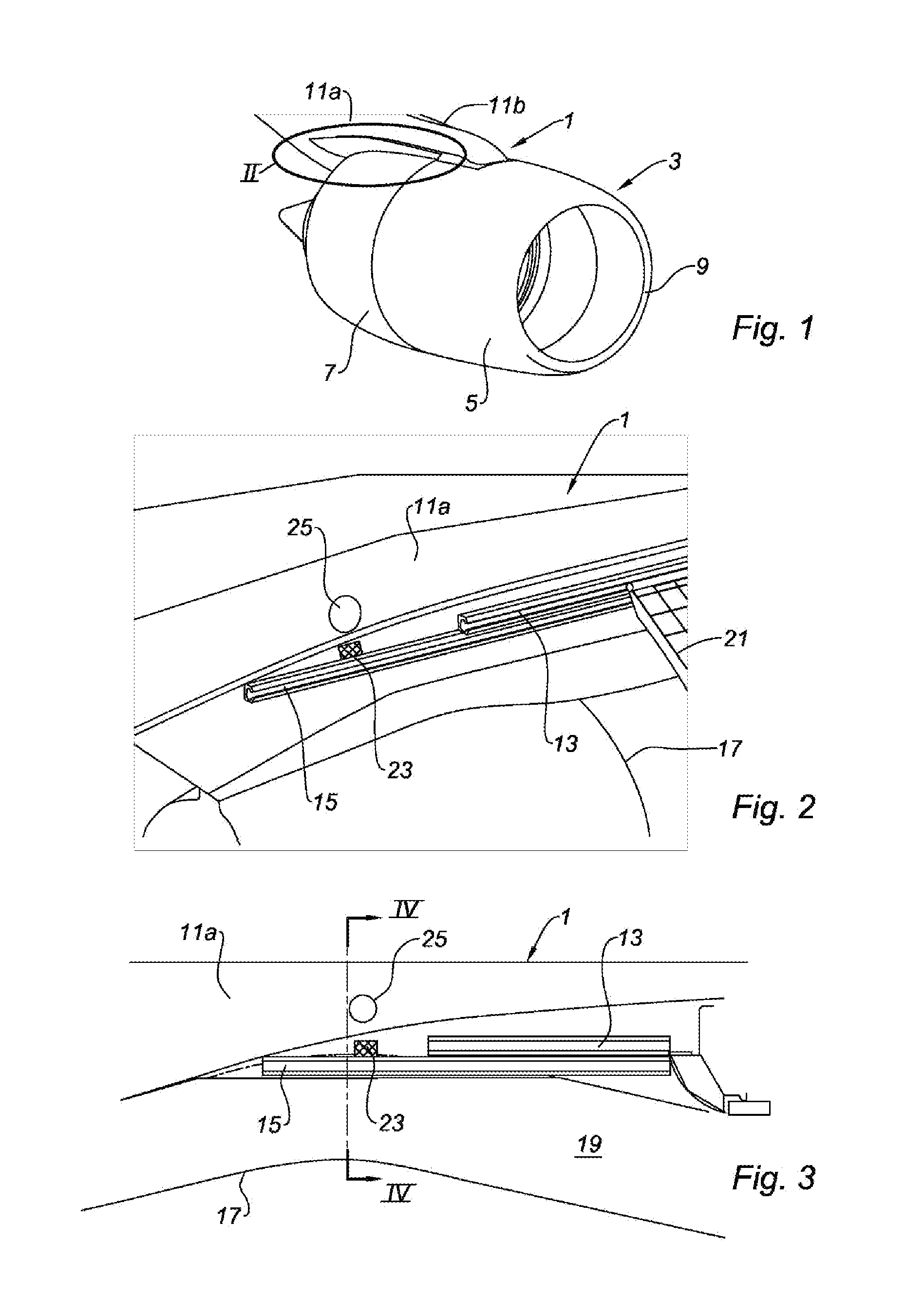
[0039]The appended FIGS. 2 to 6 show the invention.

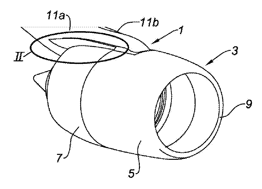
[0040]In FIGS. 2 and 3, which refer to zone II of FIG. 1 once the sliding cowl 7 has been removed, the pylon 1 is shown and, on the side 11a of said pylon, a short rail 13 and a long rail 15.

[0041]These two figures also show the inner structure 17 surrounding the turbojet engine, defining the cold air tunnel 19.

[0042]The short rail 13 allows the thrust reversal grids 21 to slide between a usage position shown in FIG. 2, and a maintenance position in which said grids are slid to the back end of the short rail 13, so as to allow access to the turbojet engine.

[0043]The long rail 15 and its counterpart positioned on the other side of the pylon 1 allow the cowl 7 to slide between its “direct jet” position and its thrust reversal position in which it frees the thrust reversal grids 21, allowing part of the air flow circulating in the tunnel 19 to be oriented toward the front of the nacelle.

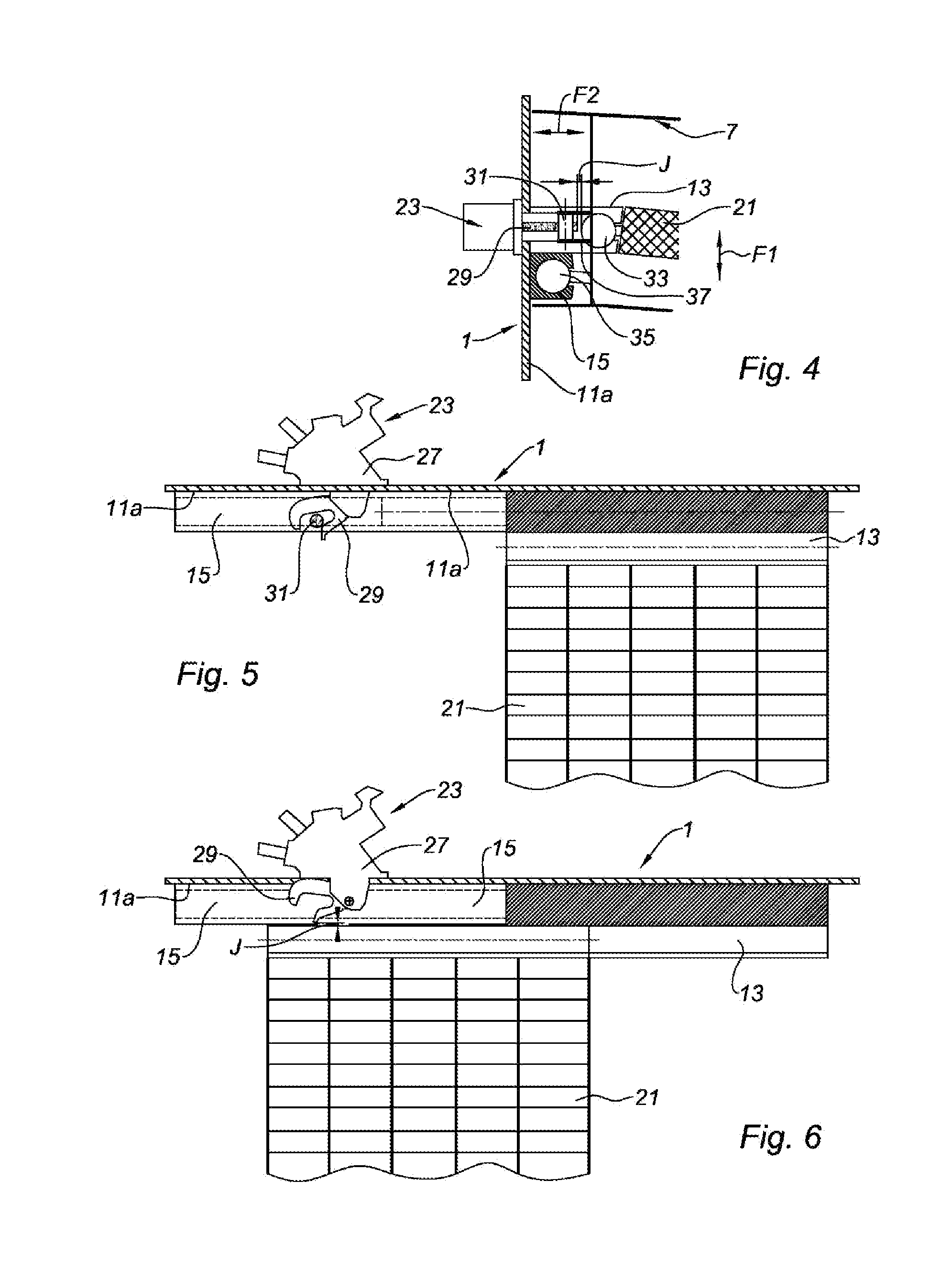
[0044]A bolt 23 is mounted inside the pylon 1, a ...


PUM


Abstract

The invention relates to an assembly for a turbojet engine which includes a pylon (1) and a nacelle supported by said pylon (1). Said nacelle (3) includes a grid thrust reverser (21) including an integral cowl mounted so as to slide on rails (15), which are arranged on both sides of said pylon (1), between a direct jet position and a thrust reversal position. Said assembly is characterised in that it includes means (23, 31) for blocking the sliding movement of the cowl on the rails (15), said means being inserted between the pylon (1) and the cowl.

Description

TECHNICAL FIELD[0001]The present invention relates to an assembly for an aircraft turbojet engine.BRIEF DESCRIPTION OF RELATED ART[0002]Known from the prior art, and in particular from document FR 2 916 426, is an assembly for a turbojet engine, comprising a pylon and a nacelle supported by said pylon, said nacelle comprising a grid thrust reverser comprising an integral cowl slidingly mounted on rails positioned on either side of said pylon between a direct jet position and a thrust reversal position.[0003]“Integral cowl” refers to a cowl with a quasi-annular shape, extending from one end of the pylon to the other without interruption. Such a cowl is often designated using the Anglo-Saxon term “O-duct,” in reference to the shroud shape of such a cowl, as opposed to a “D-duct,” which in fact comprises two half-cowls each extending over a half-circumference of the nacelle.[0004]In both cases, it is the withdrawal of the cowl by sliding along rails integral with the pylon that makes i...

Claims


Application Information

Patent Timeline
Patent Type & Authority Applications(United States)
IPC IPC(8): B64D33/04
CPCF02K1/766F02K1/72B64D29/06
Inventor CARUEL, PIERREVAUCHEL, GUY BERNARDJORET, JEAN-PHILIPPEBAILLARD, ANDRE
Owner SAFRAN NACELLES
Why Eureka
Try Eureka