Drainage body unit, drainage body system and shaft element

A technology of drainage ditch and components, which is applied in the field of filler drainage ditch unit, can solve the problems of large space and cost, and achieve the effect of increasing storage capacity

Pending Publication Date: 2020-12-18
ACO AHLMANN SE & CO KG
View PDF6 Cites 0 Cited by
  • Summary
  • Abstract
  • Description
  • Claims
  • Application Information

AI Technical Summary

Problems solved by technology

Known gutter arrangements are expensive and require a relatively large space

Method used


Image

  • Drainage body unit, drainage body system and shaft element
  • Drainage body unit, drainage body system and shaft element
  • Drainage body unit, drainage body system and shaft element

Examples


Embodiment Construction

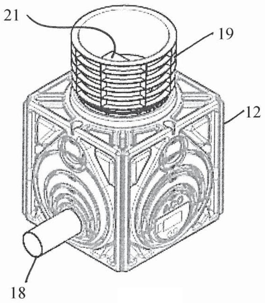
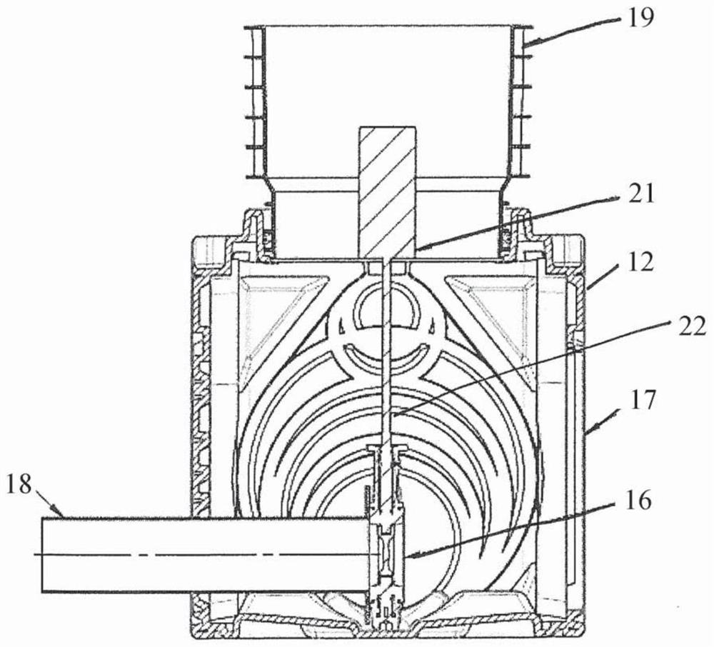
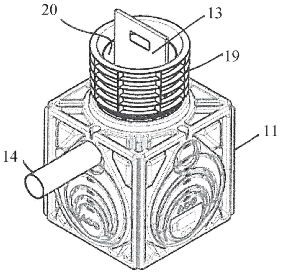
[0038] Figures 1 to 4 Shown are first and second hoistway elements 11, 12, which in accordance with Figure 5 , 6The fill gutter unit is integrated with the fill gutter element 10. The hoistway elements 11 , 12 are combined with a filler gutter unit and are disclosed and claimed individually, ie per se.

[0039] exist Figure 5 , 6 The fill gutter unit shown in can be used, for example, for rainwater retention, storage of rainwater or in combination with a fill gutter system as a fire water storage. Other applications are possible.

[0040] The fill gutter system consists of individual fill gutter elements which are sealed eg by PE film tapes or other means. Filler gutter elements are filled in use with a filler, such as gravel.

[0041] Fill gutter units as in Figure 5 , 6 As shown in , it consists of three parts, namely a first shaft element 11 with a cleaning element 13 , a second shaft element 12 with a throttle element 16 and a filler gutter element 10 .

[00...


PUM


Abstract

The invention relates to a drainage body unit having at least one drainage body element (10), at least one first shaft element (11) and at least one second shaft element (12), wherein a cleaning element (13) is arranged in the first shaft element (11) between a fluid inlet (14) and a fluid outlet (15), a throttle element (16) is arranged in the second shaft element (12) between a fluid inlet (17)and a fluid outlet (18), and the shaft elements (11, 12) are or can be fluidically connected to one or more drainage body elements (10).

Description

technical field [0001] The present invention relates to a fill gutter unit and a hoistway element for such a fill gutter unit. Background technique [0002] There are currently two problems in existing fill gutters. On the one hand, the fill drain must be protected from clogging or slugging in its interior. On the outflow side of the gutter, on the other hand, the water flow has to be adjustable, since the maximum water outflow is specified due to official regulations. For this purpose, a throttle is provided, the task of which is to relieve the downstream channel network or the downstream drainage channel. This is achieved by means of a static throttle with no moving parts or a dynamic throttle with a variable flow cross-section. A dynamic throttle keeps the outflow value constant. This results in a smaller stagnation tank, since the maximum outflow value always occurs in normal operation. At the same time, the operator can, for example, make fixed settings for clean o...

Claims


Application Information

Patent Timeline
Patent Type & Authority Applications(China)
IPC IPC(8): E03F1/00E03B3/03
CPCE03B3/03E03F1/002E03F1/005Y02A20/108E03F1/00
Inventor 海诺·梅塞施密特斯特凡·普拉克什安雅·西弗斯
Owner ACO AHLMANN SE & CO KG
Why Eureka
Try Eureka