
Photo-detector device for electro-optical sensors with variable light dynamics

a technology of electro-optical sensors and photo-detectors, applied in the field of photo-detector devices, can solve the problems of limiting the possibility of integration in a reduced space, unable to manage the reset status of individual pixels, and the image definition is not optimal, so as to achieve good immunity, high value, and efficient signal processing

Active Publication Date: 2014-07-24
EYETECH
View PDF5 Cites 0 Cited by
  • Summary
  • Abstract
  • Description
  • Claims
  • Application Information

AI Technical Summary

Benefits of technology

The present invention concerns an electro-optical sensor that can control each photo-detector device and individual pixel independently, allowing for flexible use according to different lighting zones and application requirements. The programmable reference signal ensures good quality images even in low light conditions, while the ability to analyze zones with different scene or image luminosity is achieved with programmable accuracy.

Problems solved by technology

One disadvantage of this type of electro-optical sensors is that, in the case of poor lighting, the definition of the image is not optimal.
One disadvantage of this photo-sensitive element is that it is complex, and requires a lot of space to be integrated on a silicon support or substrate, thus limiting the possibility of integration in a reduced space.
The main disadvantage of this technique is that it is necessary to associate with every photo-sensitive element a memory able to memorize the number of times that the photo-sensitive element has reached the saturation level, and a sophisticated digital control able to discriminate the need for a new reset of the photo-sensitive junction.
Using this technique, which provides to use a single generator of reference voltages, has the disadvantage that it allows to polarize the pixels, or a subset of pixels of the matrix, exclusively at a voltage value common to the whole matrix and set by the reference voltage generator.
Because of this, for example, it is not possible to manage the reset status of the individual pixel, or of a subset of selected pixels, independently of the status of the other pixels in the matrix.
Consequently, the reset status of the pixels can only be managed overall with respect to the matrix or other arrangement that comprises them.

Method used


Image

  • Photo-detector device for electro-optical sensors with variable light dynamics
  • Photo-detector device for electro-optical sensors with variable light dynamics
  • Photo-detector device for electro-optical sensors with variable light dynamics

Examples


Embodiment Construction

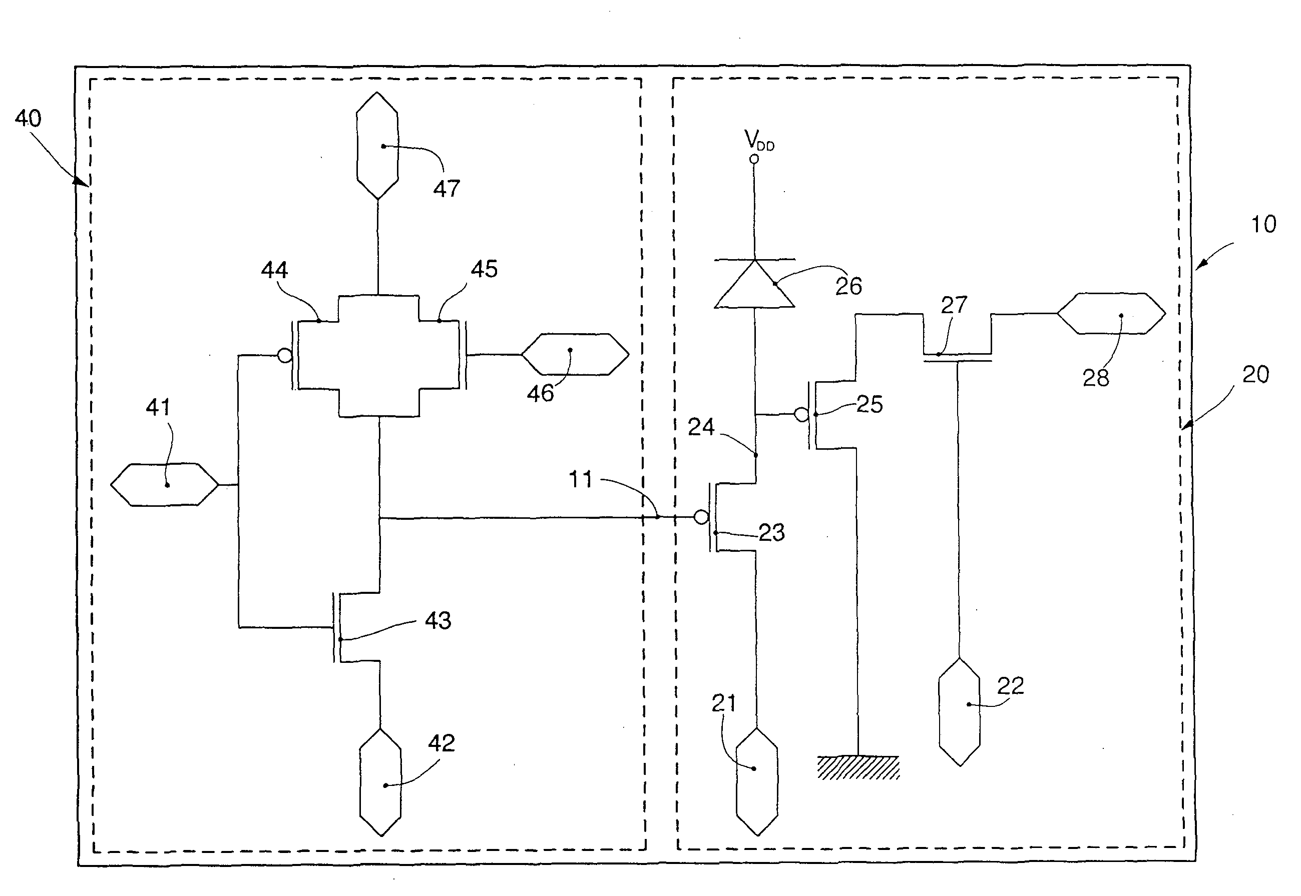
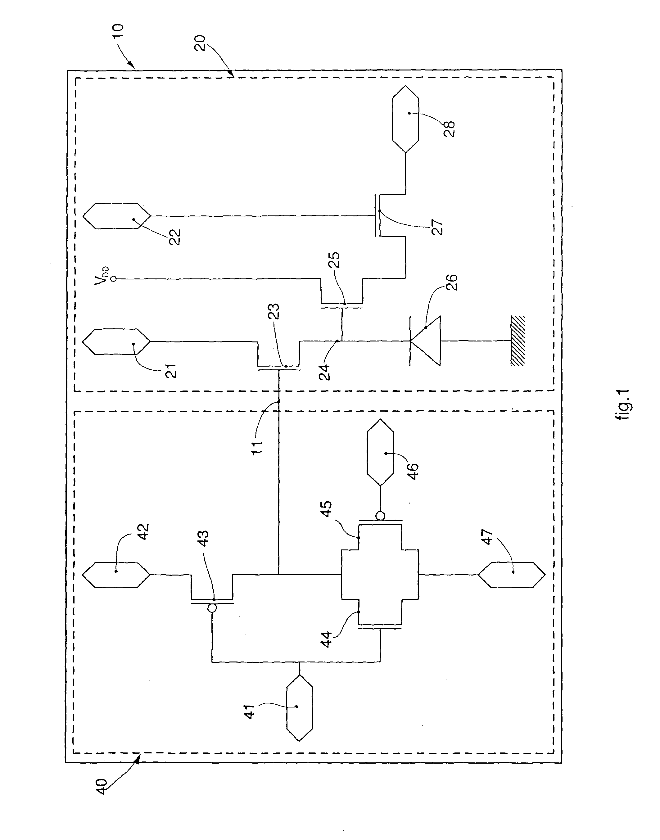
[0048]With reference to FIG. 1, a photo-detector device 10 according to the present invention comprises, in the form of embodiment shown as an example in FIG. 1:

[0049]a detection and conversion circuit 20 of the luminous signal or pixel, having an inversely polarized diode 26, sensitive to light;

[0050]an element to control the charge dissipation 23, which in this case is a MOS transistor polarized by a signal applied to an external polarization terminal 21, driven to the gate by means of a reset control signal applied to an internal reset control terminal 11;

[0051]an active amplification element 25 and

[0052]a first switch 27 in semiconductor technology driven by a signal applied to the external selection terminal 22 that carries the output signal on a read-out terminal 28.

[0053]The active amplification element 25 and the first switch 27 are made with MOS type transistors.

[0054]The photo-detector device 10 also comprises a circuit for controlling the reset voltage 40 having a second ...


PUM


Abstract

Photo-detector device for electro-optical sensors, comprising at least a detection and conversion circuit, or pixel (20), having at least a photo-sensitive reception mean (26) and a reset control terminal (11), which is able to drive an element to control the charge dissipation (23) of the photo-sensitive reception mean (26). The pixel (20) is able to convert the current generated by the photo-sensitive reception mean (26) into a voltage signal on a read-out terminal (28). The photo-detector device also comprises a circuit for controlling the reset voltage (40), able to generate a suitable input signal to the reset control terminal (11) by connecting it alternatively to a reset terminal (42) or to an external reference terminal (47), the input signal to said external reference terminal (47) is the type that can be programmed from outside. Furthermore, the circuit for controlling the reset voltage (40) can be shared between a subset of detection and control circuits (20).

Description

FIELD OF THE INVENTION[0001]The present invention concerns a photo-detector device used in electro-optical sensors, suitable to detect an incident light and to convert it into a correlated electrical signal.[0002]The photo-detector device according to the invention guarantees a high quality of the images both in conditions of low light and also when there is bright light, therefore with a light intensity varying in a wide range.[0003]The present invention is used in particular, although not exclusively, to obtain electro-optical sensors to be inserted in digital cameras, digital video cameras, smart electro-optical sensors or in biomedical devices, in particular, but not only, in instruments for endoscopic investigations.BACKGROUND OF THE INVENTION[0004]Electro-optical sensors are known, comprising a plurality of photo-detector devices suitable to detect light signals by means of a photo-sensitive element, and to transmit them in the form of electrical signals to a calculator unit t...

Claims


Application Information

Patent Timeline
IPC IPC(8): H04N5/355H04N5/378
CPCH04N5/378H04N5/355H04N25/59H04N25/78H04N25/57H04N25/75
Inventor VATTERONI, MONICA
Owner EYETECH
Learn More