
Iron core member of a resolver

a resolver and iron core technology, applied in the field of resolvers, can solve the problems of deteriorating the working result of the resolver, too high iron loss, and lack of iron core members for easy winding and positioning enameled wires, and achieve the effect of low iron loss

Inactive Publication Date: 2012-09-13
HIWIN MIKROSYST
View PDF2 Cites 3 Cited by
  • Summary
  • Abstract
  • Description
  • Claims
  • Application Information

AI Technical Summary

Benefits of technology

The present invention provides an iron core member for a resolver with lower iron loss. The iron core member has a curved shape with multiple pole sections evenly spaced around its outer edge. Each pole section has a recessed section on its periphery. The core section and pole sections are made of iron powder. This design helps to reduce the energy loss when the resolver is in use.

Problems solved by technology

Under such a high-frequency circumstance, in case the iron core member of the resolver is composed of silicon steel sheets, the silicon steel sheets will lead to too high iron loss.
Therefore, with respect to the conventional technique, the too high iron loss will deteriorate the working result of the resolver.
Also, the iron core member lacks any structure for easily winding and locating the enameled wires.
As a result, the manufacturing and assembling efficiency is low.
Also, the stability of the manufacturing process and the reliability of the product are poor.
Therefore, in the case that the number of the poles is increased to enhance the precision, the winding process will be more complicated and troublesome.
This is an obstacle to the promotion of the quality of the resolver.

Method used


Image

  • Iron core member of a resolver
  • Iron core member of a resolver
  • Iron core member of a resolver

Examples


Embodiment Construction

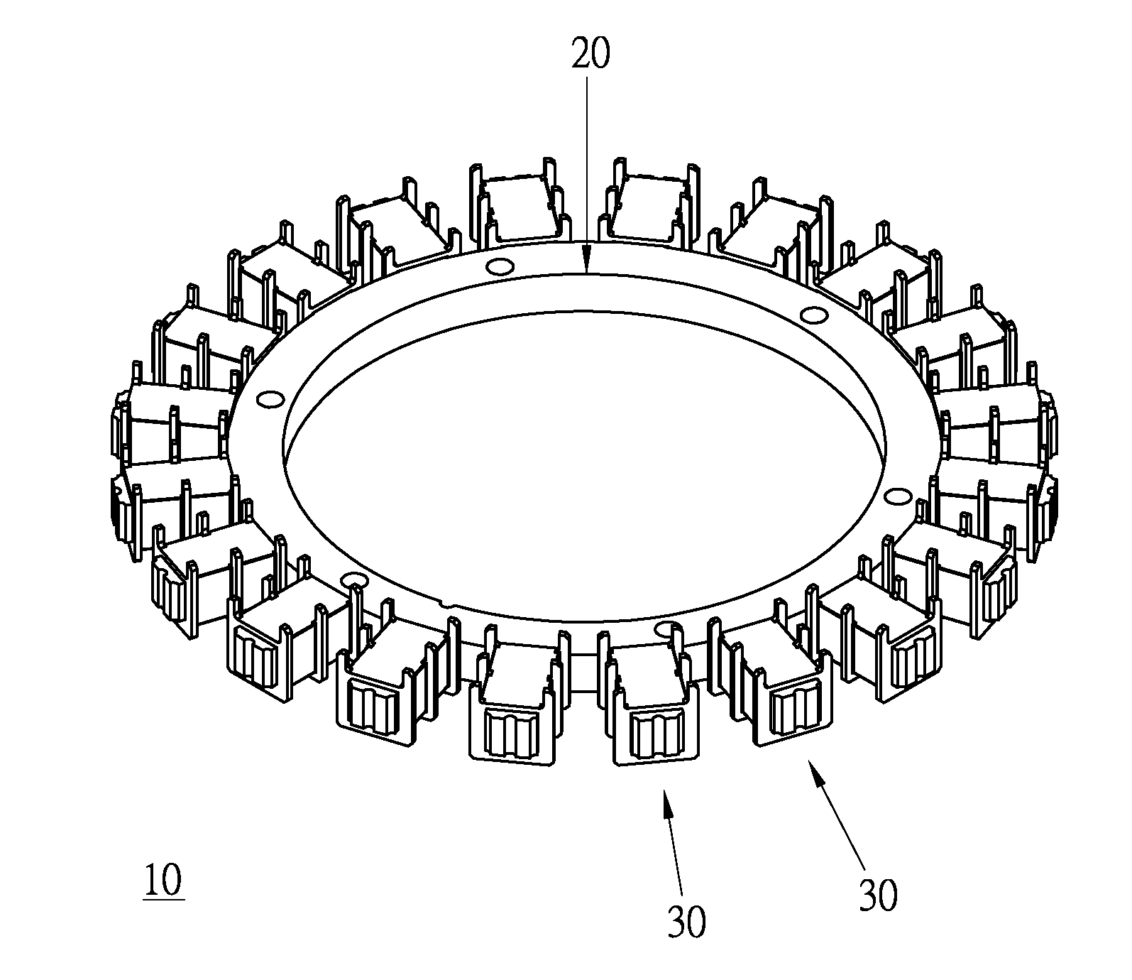
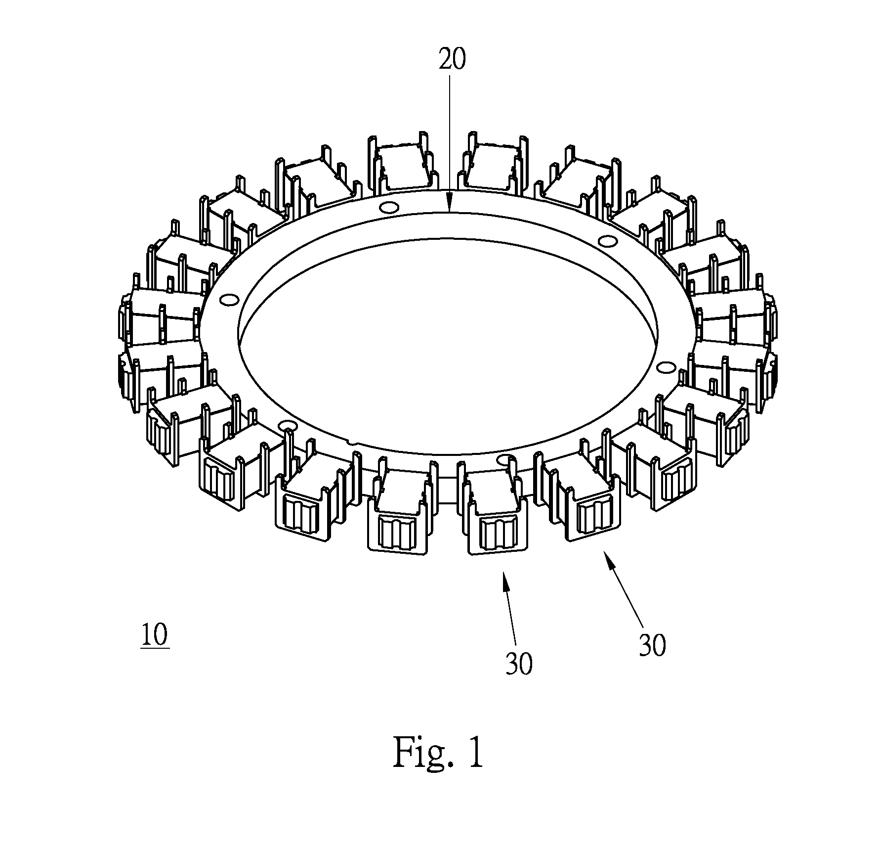
[0014]Please refer to FIGS. 1 and 2. According to a preferred embodiment, the iron core member 10 of the resolver of the present invention is applied to a stator of a magnetoresistive resolver. The iron core member 10 includes a core section 20 and multiple pole sections 30. The core section 20 and the pole sections 30 are integrally formed of iron powder by die-casting.

[0015]The core section 20 is an annular plate body with a curvature center.

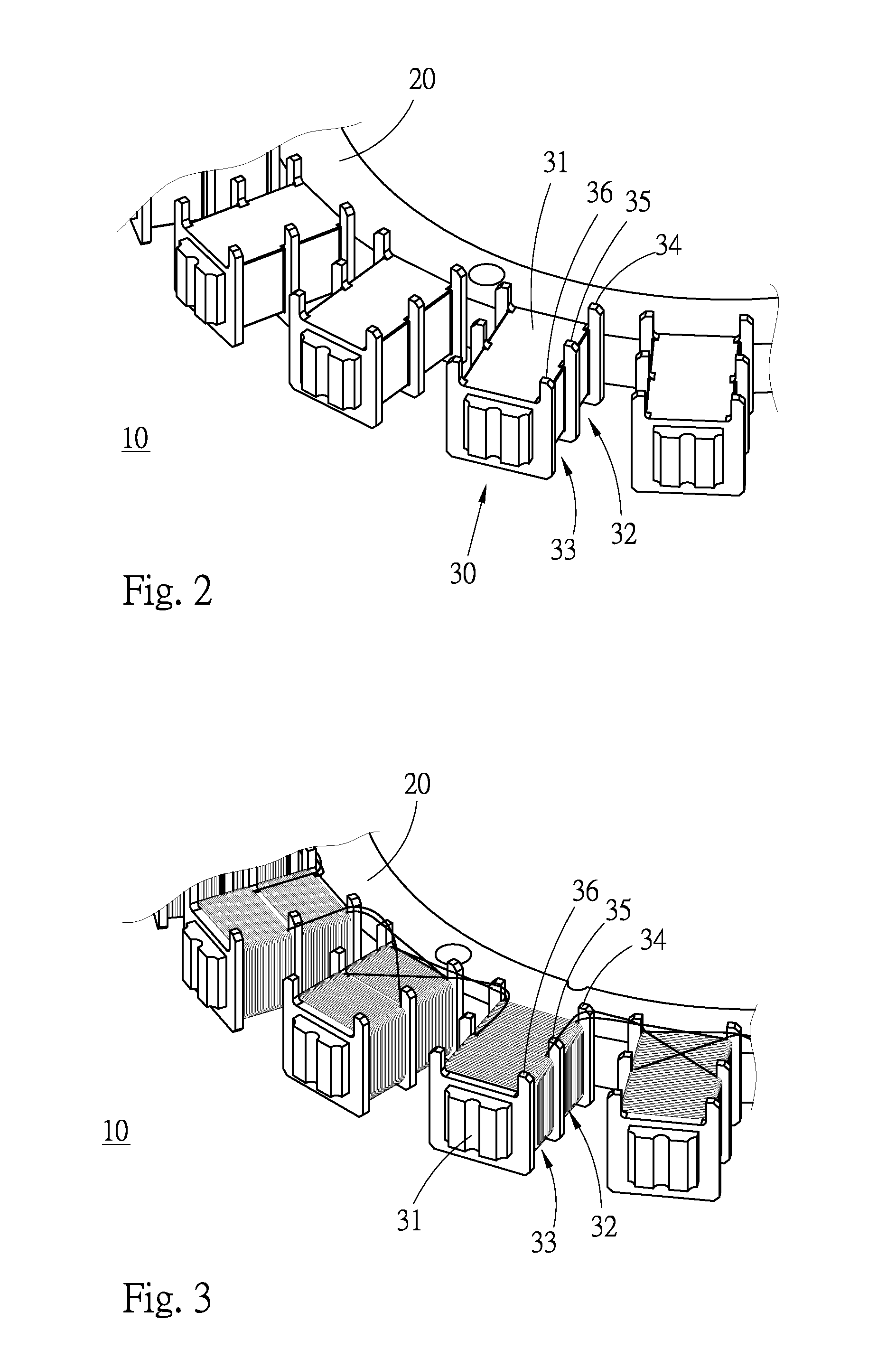
[0016]The pole sections 30 are annularly arranged on outer circumference of the core section 20 at equal intervals and centered at the curvature center of the core section 20. The pole sections 30 project from the outer circumference of the core section 20. Each pole section 30 has a substantially rectangular solid pole body 31. A first end of the pole body 31 is connected to the outer circumference of the core section 20. A periphery of the pole body 31 is recessed to form a first recessed section 32 and a second recessed section 33. The firs...


PUM


Abstract

An iron core member of a resolver, which is a one-piece member integrally formed of iron powder. The iron core member includes an annular core section and multiple pole sections annularly arranged on outer circumference of the core section at equal intervals and projecting from the outer circumference of the core section. Each pole section has recessed sections. Enameled wires can be conveniently wound around the recessed sections to form coils located in the recessed sections. The pole section further has multiple projection posts. After the winding process is completed, the terminals of the enameled wires are hooked and located on the projection posts. In comparison with the conventional iron core member, the present iron core member has lower iron loss and the manufacturing process is simplified.

Description

BACKGROUND OF THE INVENTION[0001]1. Field of the Invention[0002]The present invention relates generally to a resolver, and more particularly to an iron core member of a resolver.[0003]2. Description of the Related Art[0004]A conventional resolver is used to feed back angular positions of a motor to a drive device. The conventional resolver includes excitation coils and induction coils. The excitation coils serve as excitation signal sources to provide excitation signals. The induction coils serve to sense magnetic field change and achieve corresponding amplitude modulation signals to feed back signals of angular position of the motor. In structure, the coils are formed of enameled wires, which are wound on the poles of the iron core member of the resolver. After the winding process is completed, the terminals of the enameled wires must be manually affixed to the coils by means of a suitable adhesive.[0005]Moreover, the conventional iron core member is composed of multiple stacked si...

Claims


Application Information

Patent Timeline
Patent Type & Authority Applications(United States)
IPC IPC(8): G01B7/30
CPCG01D5/204
Inventor TENG, CHAO-CHINLI, CHI-LUWANG, HSIANG-JU
Owner HIWIN MIKROSYST
Learn More