Method of measuring height and detecting obstacles, a radioaltimeter, and an aircraft
Active Publication Date: 2012-09-13
EUROCOPTER
View PDF11 Cites 13 Cited by
Summary
Abstract
Description
Claims
Application Information
AI Technical Summary
This helps you quickly interpret patents by identifying the three key elements:
Problems solved by technology
Method used
Benefits of technology
Benefits of technology
[0014]Document EP 1 617 243 presents a car radar device seeking to reduce the disturbances caused by the ground.
[0019]An object of the present invention is thus to provide a device that serves to avoid having too many pieces of equipment.
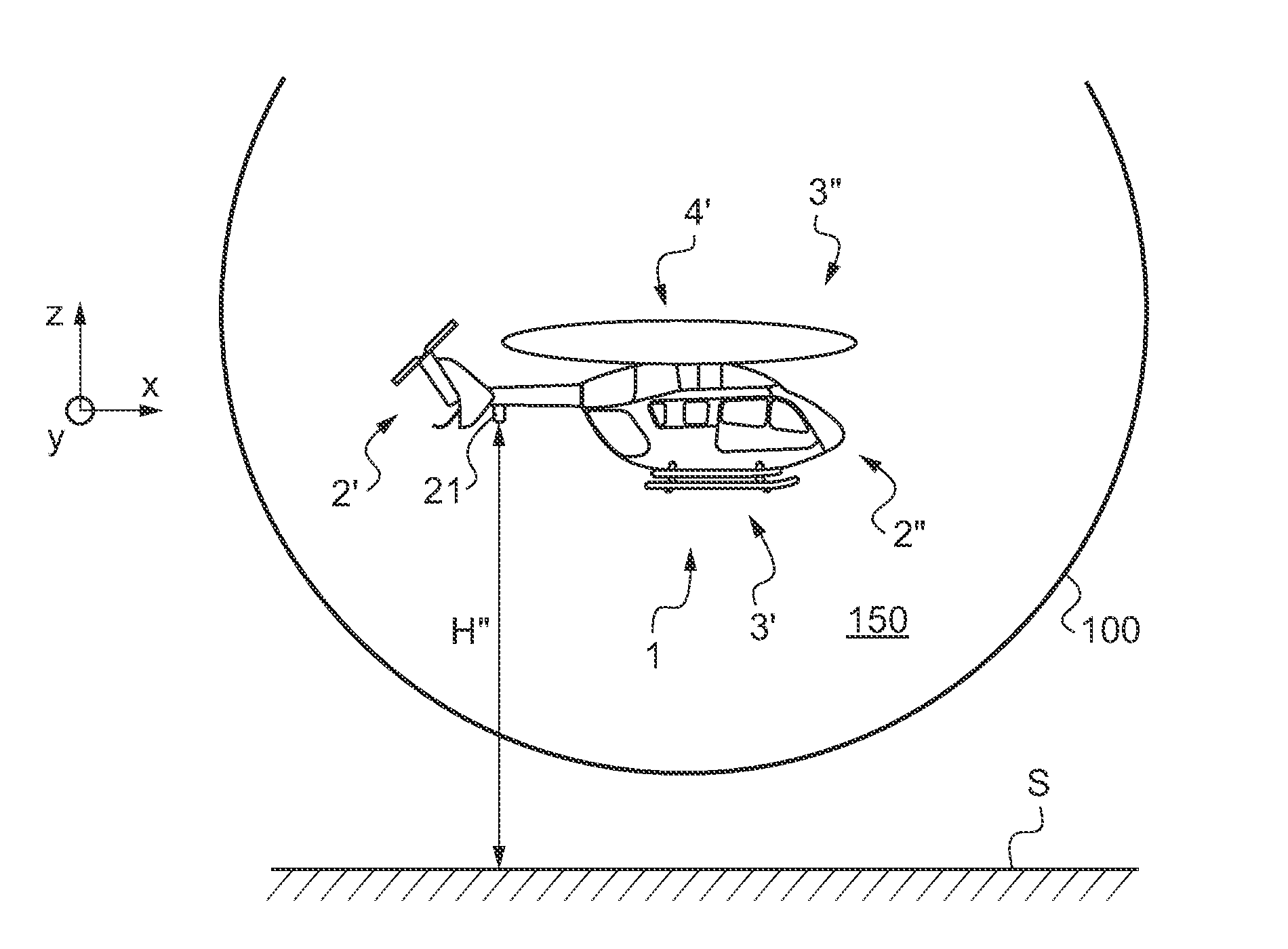
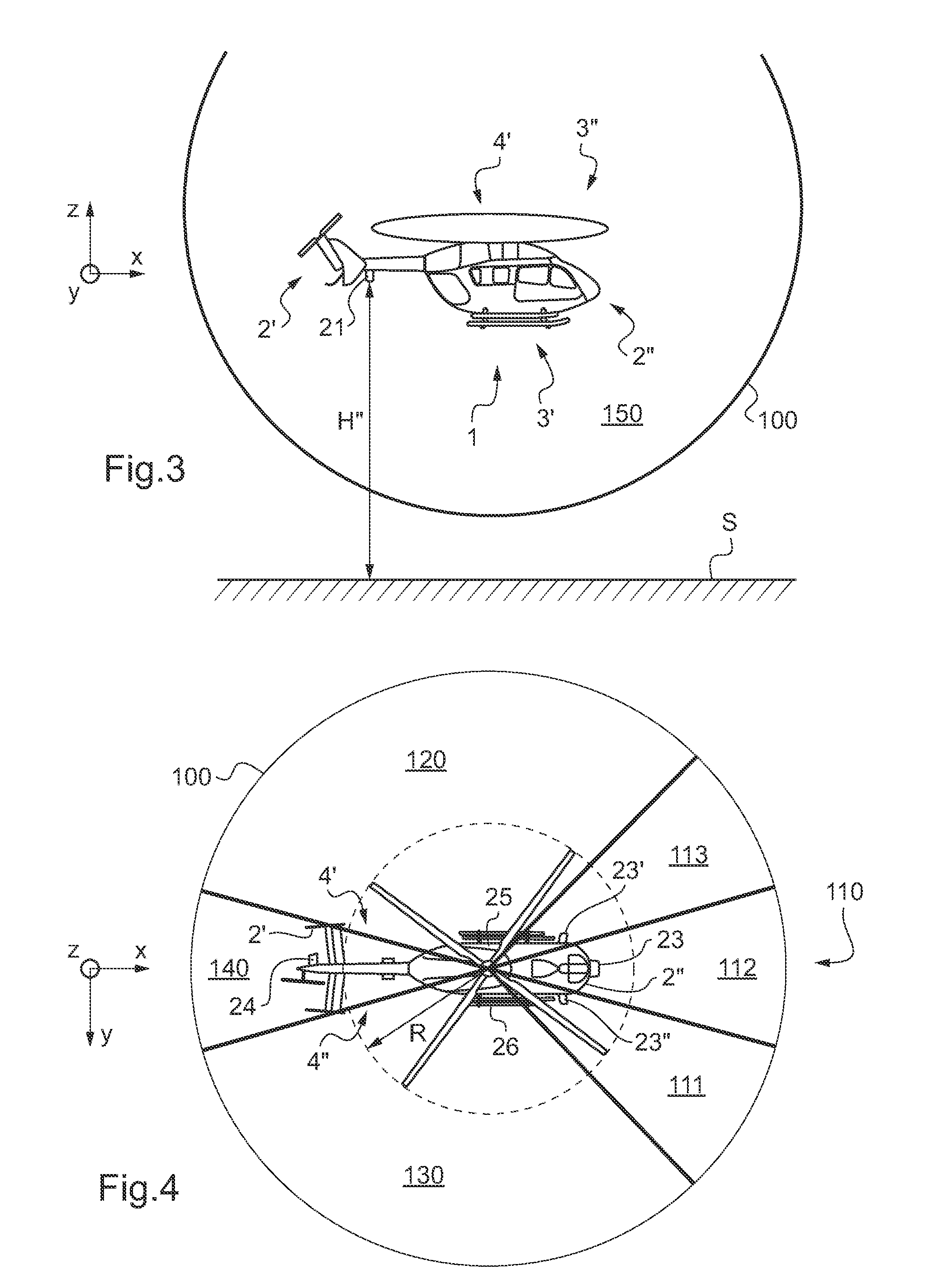
[0022]Consequently, the radioaltimeter serves not only to measure the height between the aircraft and the overflown ground, the aircraft being vertically above said ground, but is capable, surprisingly, of detecting obstacles that are present in a spherical volume surrounding the aircraft. As a result there is no need to implement a dedicated detection system in addition to a radioaltimeter.
[0027]It should be observed that in the method explained below, it is possible to modify the cycle for switching the transceiver members once an obstacle has been detected in order to monitor more closely the risky sector in which the obstacle is located, but without that restricting detection to said risky sector only.
[0055]The various secondary members are designed to operate at the same transmit / receive frequency, however they could equally well operate at different wavelengths, it being possible for the front secondary member to operate over a long range, for example, while the rear secondary member and the left and right side secondary members operate over a short range.
[0071]When the forward speed is high, e.g. greater than or equal to 50 knots, for example, it is found to be advantageous to monitor the time up to a potential impact in a direction relative to the forward advance of the aircraft.
Problems solved by technology
Nevertheless, that instrument is not designed to detect obstacles other than the overflown terrain.
Method used
Image
Click on the blue label to locate the original text in one second.
Reading with bidirectional positioning of images and text.
Examples
first embodiment
[0085]FIG. 1 shows an aircraft 1, represented diagrammatically and having a radioaltimeter 5 in the invention.
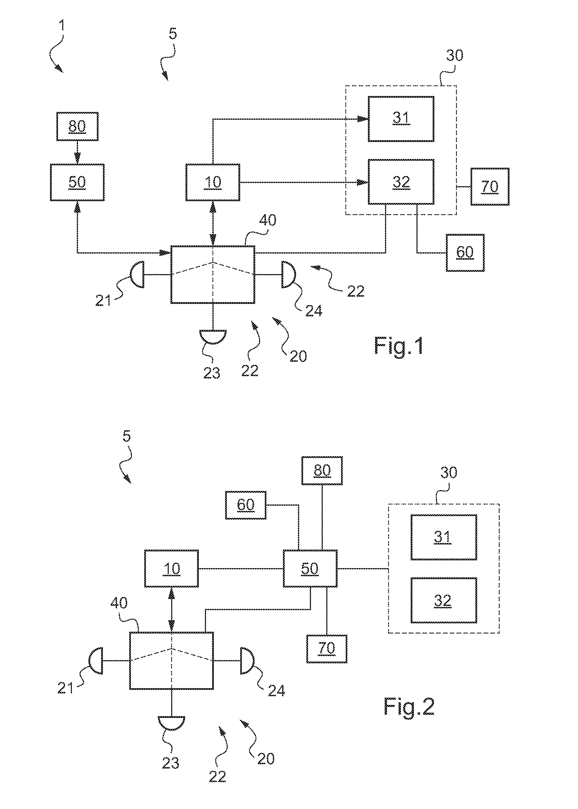
[0086]Independently of the embodiment, the radioaltimeter 5 comprises a signal generator-receiver 10, e.g. of the radiowave type. This generator-receiver 10 may be for example of the type present in radioaltimeters prior to the invention.
[0087]The generator-receiver 10 thus generates a signal and measures the time taken by the signal to return to the aircraft after being reflected by an obstacle. Given the propagation speed of the signal, which is known and constant, the generator-receiver 10 determines the distance between the aircraft 1 and the obstacle, i.e. the ground or an obstacle that is other than the ground, for example.
[0088]In order to transmit the signal generated by the generator-receiver 10, and in order to receive the resulting reflected signal, the radioaltimeter 5 includes transceiver means 20 connected indirectly to the generator-receiver 10.
[0089]The trans...
second embodiment
[0114]With reference to FIG. 2, in a second embodiment, the control unit is connected in particular to the display means 30, to the switch means 40, to the generator-receiver 10, to the detection means of the position-determination member 60, and to the alarm means 70.
[0115]Independently of the embodiment, the radioaltimeter 5 makes use of a method for making the flight of an aircraft safe so as to avoid the aircraft striking the ground or an obstacle other than the ground.
[0116]In a first step of the method, the radioaltimeter 5 transmits signals at a given cycle into a plurality of sectors of a spherical volume 100 surrounding the aircraft.
[0117]On each cycle, the radioaltimeter 5 transmits in succession a signal into a main sector in order to determine the height of the aircraft relative to the ground over which it is flying, i.e. the ground vertically below the aircraft, and a signal in at least one secondary sector of the spherical volume 100 in order to detect the presence of ...
PUM
Abstract
A radioaltimeter (5) having a signal generator-receiver (10) and signaltransceiver means (20) connected to the generator-receiver (10), and a display member (30), said transceiver means (20) comprising a transceiver main member (21) for sending a signal towards a ground (S) in order to determine the height (H) between said main member (21) and said ground (S), said display member (30) having main display means (31) for displaying said height (H). Furthermore, the radioaltimeter (5) includes switch means (40) together with a control unit (50), and secondary display means (32) of said display member (30).
Description
CROSS REFERENCE TO RELATED APPLICATIONS[0001]This application claims priority to French patent application FR 11 00733 filed on Mar. 11, 2011.BACKGROUND OF THE INVENTION[0002](1) Field of the Invention[0003]The present invention relates to a method of measuring a height and of detecting obstacles, to a radioaltimeter, and to an aircraft.[0004](2) Description of Related Art[0005]The invention thus lies in the technical field of detecting obstacles from on board an aircraft.[0006]An aircraft is usually provided with a plurality of flight instruments. Such flight instruments may include a radioaltimeter that serves to determine the height between the aircraft and the overflown ground.[0007]Such a radioaltimeter may include a generator-receiver for generating and receiving signals such as radiowaves, the signal generator-receiver co-operating with signal transceiver means and with display means. The transceiver means may comprise either an antenna suitable for transmitting and receiving...
Claims
Application Information
Patent Timeline
Application Date:The date an application was filed.
Publication Date:The date a patent or application was officially published.
First Publication Date:The earliest publication date of a patent with the same application number.
Issue Date:Publication date of the patent grant document.
PCT Entry Date:The Entry date of PCT National Phase.
Estimated Expiry Date:The statutory expiry date of a patent right according to the Patent Law, and it is the longest term of protection that the patent right can achieve without the termination of the patent right due to other reasons(Term extension factor has been taken into account ).
Invalid Date:Actual expiry date is based on effective date or publication date of legal transaction data of invalid patent.

