Gyro Mouse De-Drift and Hand Jitter Reduction

a mouse and hand technology, applied in the field of gyroscopes, can solve the problems of high cost, mouse cost, high cost, etc., and achieve the effect of high accuracy

Active Publication Date: 2012-09-13
SEIKO EPSON CORP
View PDF2 Cites 26 Cited by
  • Summary
  • Abstract
  • Description
  • Claims
  • Application Information

AI Technical Summary

Benefits of technology

[0015]It is an object of the present invention to provide a gyroscope-based mouse that utilizes inexpensive gyroscopes, bu

Problems solved by technology

This technology offered relatively high accuracy, as determined by the pitch of the grid lines, but was hindered by high cost and the need for specialized reflective grid surfaces.
This reduced the cost of the mouse and removed the need for a reflective grid surface, but offered lower accuracy and reliability.
However, mouse movement was still restricted to a planar surface.
First is a limitation of the gyroscope technology itself.
To make a commercially viable mouse, requires the use of relatively inexpensive gyroscopes, which unfortunately are prone to drift error.
This motional drift is typically small, but cumulative, and its cumulative effect can cause a computer cursor to drift in an unintended manner.
Another limitation of the gyroscope-based mouse

Method used


Image

  • Gyro Mouse De-Drift and Hand Jitter Reduction
  • Gyro Mouse De-Drift and Hand Jitter Reduction
  • Gyro Mouse De-Drift and Hand Jitter Reduction

Examples


Embodiment Construction

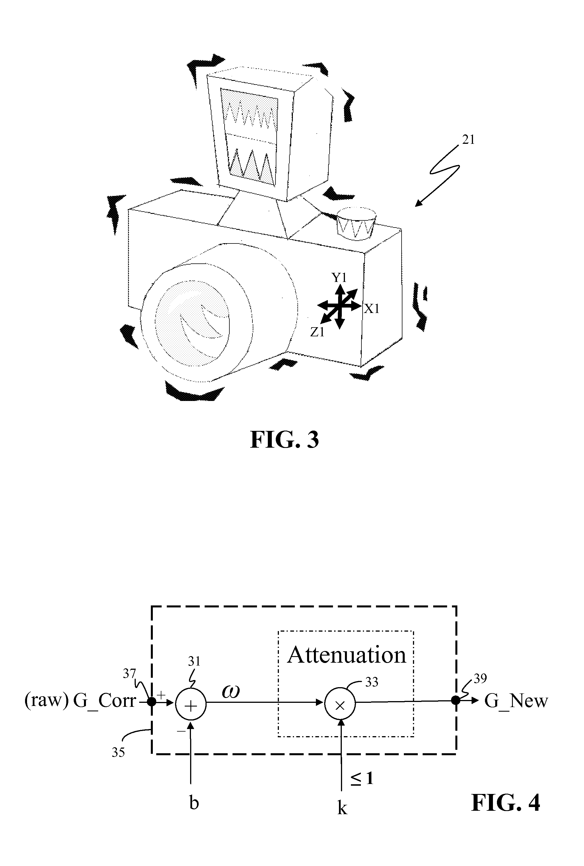
[0045]It has been found that in a three-dimensional (3D) environment (i.e. an environment with an x-axis, y-axis, and z-axis), translation of 3D movement to a computer cursor on a two-dimensional (2D) surface (i.e. a flat computer screen, or image) is achievable by monitoring mouse movement in only two of the three axes.

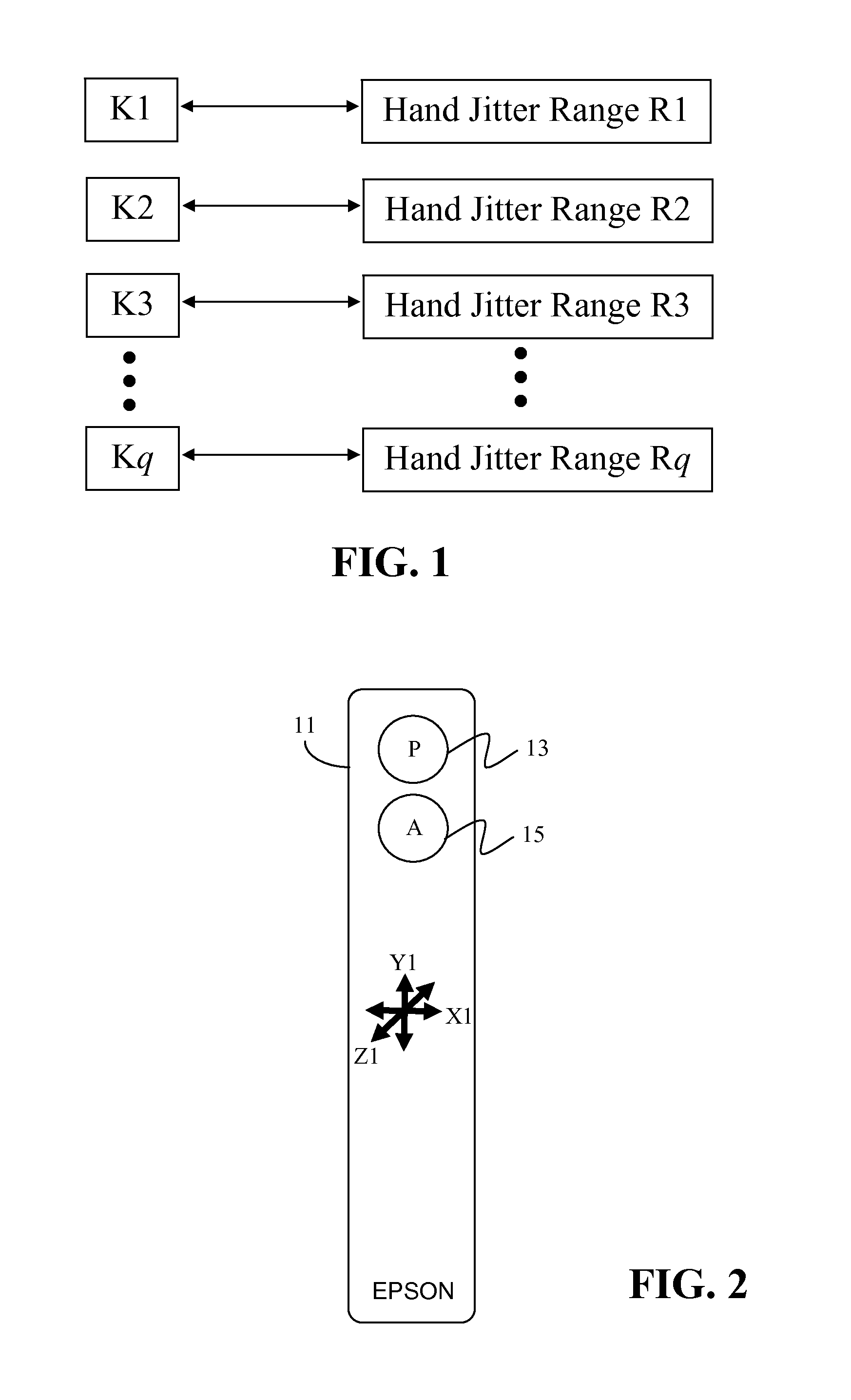
[0046]That is, good translation of mouse movements to intended cursor movements is achievable by a dual-axis gyroscope, i.e. a gyroscope limited to monitoring to two axes. It has further been found that a dual-axis gyroscope that includes an x-axis gyroscope for monitoring x-axis motion and a z-axis gyroscope for monitoring z-axis motion is sufficient for accurately controlling a computer cursor on a two-dimensional screen.

[0047]Therefore, a preferred application of the present invention is a dual-axis gyroscope-based mouse, or Gyro mouse. However, since the present invention is disclosed as applied individually to each gyroscope of a multi-gyroscope system (i.e. a G...


PUM


Abstract

A gyroscope-based device uses a probability model to assign probability of the device being in an intended static state to each received sample of gyroscope data. A new drift error compensation offset and new hand jitter factor are computed for each sample of gyroscope data based on the assigned probability. In this manner, the magnitude of the hand jitter factor varies with the probability of the device being in an intended static state.

Description

BACKGROUND[0001]1. Field of Invention[0002]The present invention relates to gyroscopes integrated into handheld devices. More specifically, it relates to methods / systems for mitigating gyroscope drift error and hand jitter error in such devices.[0003]2. Description of Related Art[0004]A computer mouse is a type of computer input device. A common form of these input devices is the planar-surface-based computer mouse, which is moved on a planar surface to control a computer cursor on a screen, with movements of the cursor corresponding to movements of the mouse. Objectives in the design of a computer mouse are versatility, accuracy, ease of use, and intuitiveness of corresponding movements between the mouse and the cursor on the screen.[0005]Computer mouse technology has undergone various permutations over the years. An early computer mouse technology used a light beam emanated from under the mouse onto a planar, reflective surface covered with a grid line pattern. Mouse movement was ...

Claims


Application Information

Patent Timeline
IPC IPC(8): G06F3/033G06F3/038
CPCG06F3/0346H04N5/23258G06F3/038G06F3/03543H04N23/6812
Inventor FU, GUOYI
Owner SEIKO EPSON CORP
Why Eureka
Try Eureka