Resistive multi-touch device and method for detecting touched points of the resistive multi-touch device thereof

a multi-touch device and resistive technology, applied in the field of resistive multi-touch devices, can solve the problems of increasing the time for detecting the location of touch points, not enough space to accommodate traditional input devices such as keyboards or mice, etc., and achieve the effect of improving the scanning tim

Inactive Publication Date: 2012-09-13
HIMAX TECH LTD
View PDF10 Cites 11 Cited by
  • Summary
  • Abstract
  • Description
  • Claims
  • Application Information

AI Technical Summary

Benefits of technology

[0013]It is one of the objectives of the present invention to improve the scanning time for detecting multi touches on the resistive multi-touch device by adopting the predetermined scanning mode (such as, the sequence scanning mode, the row scanning mode, the column scanning mode, or the matrix scanning mode) disclosed in the present invention.

Problems solved by technology

Currently, the electronic products are usually designed with the trend of light weight and small size, hence there is no enough space to accommodate traditional input devices such as keyboards or mice.
However, with the increasing size of the touch panel and the increasing number of the touch points, the time for detecting locations of the touch points is increased due to parasitic resistance and capacitance effects.

Method used


Image

  • Resistive multi-touch device and method for detecting touched points of the resistive multi-touch device thereof
  • Resistive multi-touch device and method for detecting touched points of the resistive multi-touch device thereof
  • Resistive multi-touch device and method for detecting touched points of the resistive multi-touch device thereof

Examples


first embodiment

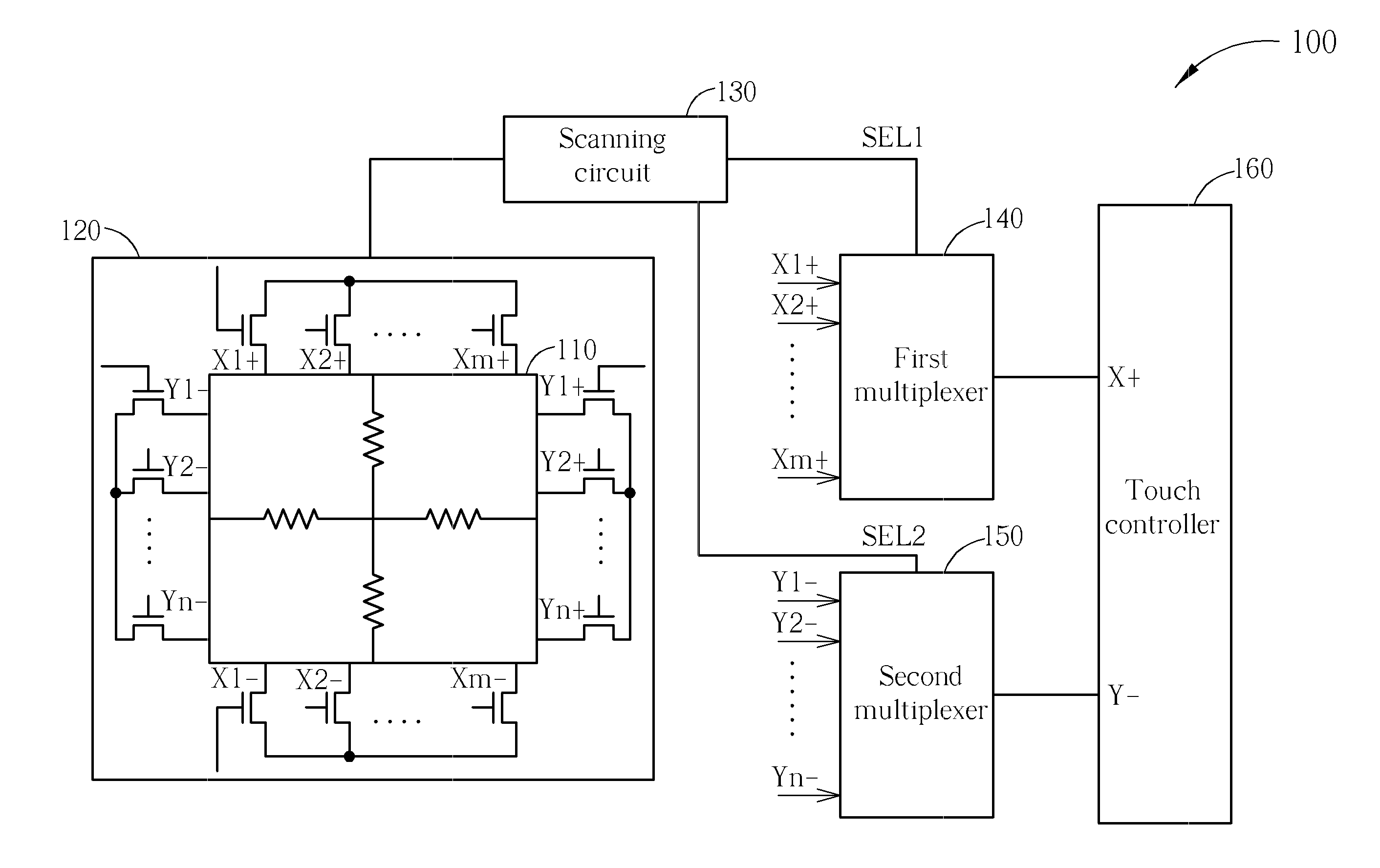
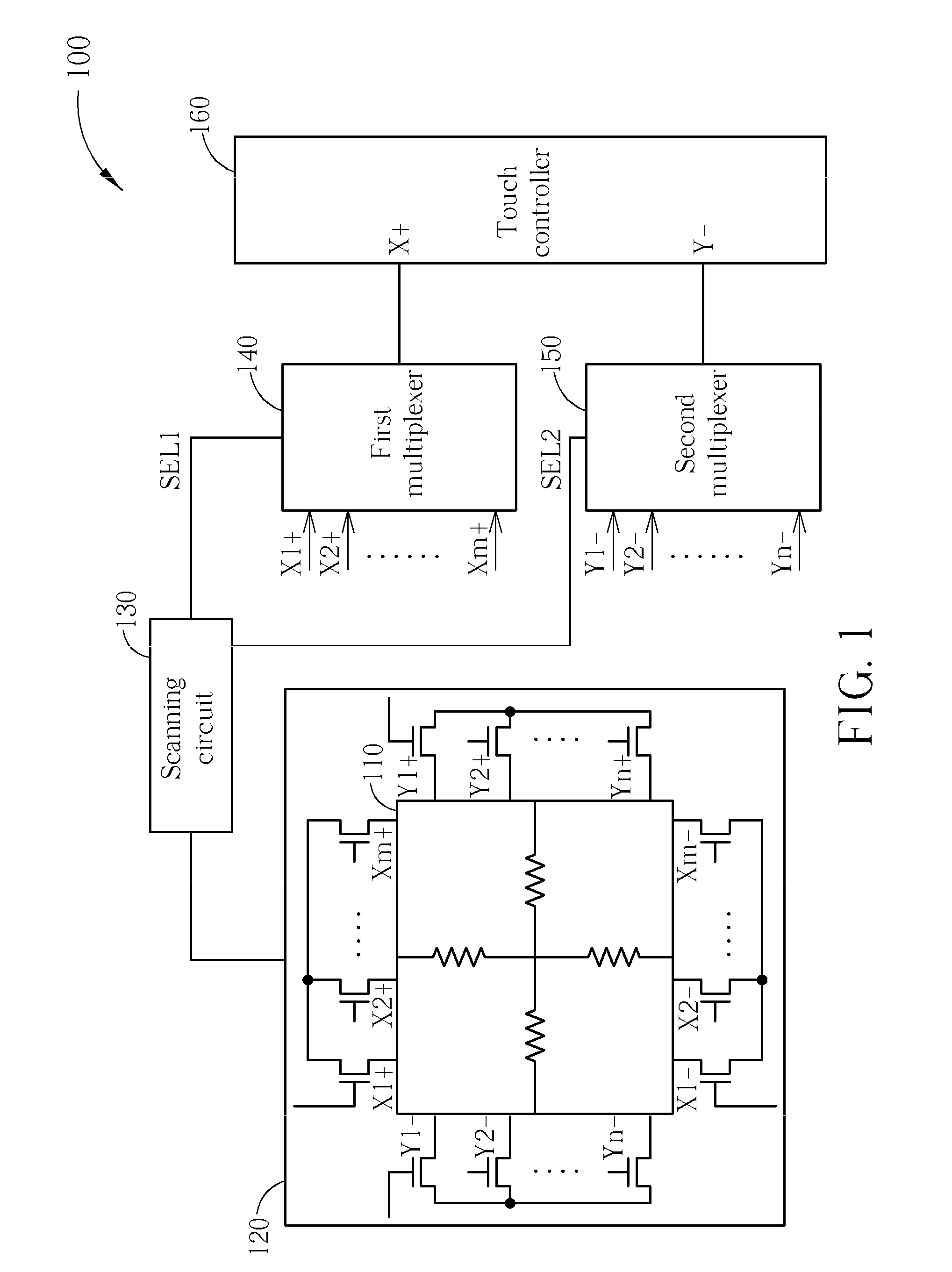
[0036]Please refer to FIG. 3. FIG. 3 is a diagram illustrating a predetermined scanning mode adopted by the scanning circuit shown in FIG. 1 according to the present invention. In this embodiment, the predetermined scanning mode is a sequence scanning mode. As shown in FIG. 3, the matrix 120 includes m pairs of first electrodes X1˜Xm arranged along the X direction to form m columns of the matrix 120 and n pairs of second electrodes Y1˜Yn arranged along the Y direction to form n rows of the matrix 120. Please note that in this embodiment, the scanning circuit 130 sequentially detects which column of the m pairs of first electrodes X1˜Xm is touched and detects which row of the n pairs of second electrodes Y1˜Yn is touched one-by-one from a left-up corner LU to a right-down corner RD of the matrix 120.

second embodiment

[0037]Please refer to FIG. 4. FIG. 4 (including sub-diagrams 4A and 4B) is a diagram illustrating a predetermined scanning mode adopted by the scanning circuit shown in FIG. 1 according to the present invention. In this embodiment, the predetermined scanning mode is a row scanning mode. As shown in 4A, a designated second electrode (i.e., Y1−) is switched on while the other (n−1) second electrodes Y2−˜Yn− are switched off, and all of the m first electrodes X1+˜X1m+ are switched on in order to check whether the row corresponding to the designated second electrode Y1− is touched. As shown in 4B, if the row corresponding to the designated second electrode Y1− is touched, the designated second electrode Y1− is switched on, and the m first electrodes X1+˜X1m+ are sequentially switched on one-by-one in order to check which column of the m first electrodes X1+˜X1m+ is touched. For example, during a period T1, the second electrode Y1− is switched on and the first electrode X1+ is switched o...

third embodiment

[0038]Please refer to FIG. 5. FIG. 5 (including sub-diagrams 5A and 5B) is a diagram illustrating a predetermined scanning mode adopted by the scanning circuit shown in FIG. 1 according to the present invention. In this embodiment, the predetermined scanning mode is a column scanning mode. As shown in 5A, a designated first electrode (i.e., the X1+) is switched on while the other (m−1) first electrodes X2+˜Xm+ are switched off, and all of the n second electrodes Y1−˜Yn− are switched on in order to check whether the column corresponding to the designated first electrode X1+ is touched. As shown in 5B, if the column corresponding to the designated first electrode X1+ is touched, the designated first electrode X1+ is switched on, and the n second electrodes Y1−˜Yn− are sequentially switched on one-by-one in order to check which row of the n second electrodes Y1−˜Yn− is touched. For example, during a period T1, the first electrode X1+ is switched on and the second electrode Y1− is switc...


PUM


Abstract

A resistive multi-touch device includes a touch panel, a matrix, a scanning circuit, a first multiplexer, a second multiplexer, and a touch controller. The matrix includes m pairs of first electrodes forming m columns and n pairs of second electrodes forming n rows. The scanning circuit detects which column of first electrodes is touched to generate a first selecting signal and which row of second electrodes is touched to generate a second selecting signal according to a predetermined scanning mode. The first multiplexer selects a first signal of the touched first electrode from signals transmitted on the first electrodes according to first selecting signal. The second multiplexer selects a second signal of the touched second electrode from signals transmitted on the second electrodes according to second selecting signal. The touch controller calculates coordinate value of touched point according to first signal and second signal.

Description

BACKGROUND OF THE INVENTION[0001]1. Field of the Invention[0002]The present invention relates to an resistive multi-touch device, and more particularly, to an resistive multi-touch device and a related method for detecting touched points of the resistive multi-touch device according to a predetermined scanning mode.[0003]2. Description of the Prior Art[0004]In today's consumer electronics markets, portable electronic products such as personal digital assistants (PDAs), mobile phones, and PDA phones have already adopted a touch panel as their interface tool for data communication. Currently, the electronic products are usually designed with the trend of light weight and small size, hence there is no enough space to accommodate traditional input devices such as keyboards or mice. Especially with the demands for human nature design in Tablet PCs, display devices equipped with a touch panel are becoming an important component of a variety of electronic products.[0005]A resistive multi-t...

Claims


Application Information

Patent Timeline
Patent Type & Authority Applications(United States)
IPC IPC(8): G06F3/045
CPCG06F3/0416G06F2203/04104G06F3/045G06F3/04166
Inventor FANG, YING-LINWU, CHANG-LUNGWENG, MING-HUNG
Owner HIMAX TECH LTD
Why Eureka
Try Eureka