Printing device and method for printing a printing substrate

a printing substrate and printing device technology, applied in printing, other printing apparatus, etc., can solve the problems of the inability to achieve finite accuracy regarding the control of the run of the web, and the inability to print accurately. the effect of printing errors

Inactive Publication Date: 2012-09-13
EASTMAN KODAK CO
View PDF17 Cites 7 Cited by
  • Summary
  • Abstract
  • Description
  • Claims
  • Application Information

AI Technical Summary

Benefits of technology

[0005]The object of the invention is to reduce printing errors that result from an erroneous alignment of at least one first printing unit relative to at least one second printing unit due to transverse movements of a printing substrate during the printing operation.

Problems solved by technology

However, the run of the web may be subject to fluctuations, and only finite accuracy can be achieved regarding the control of the run of the web.
In addition, the application of a printing ink inside the printhead, for example, may also lead to a transverse movement of the web, which movement—as a rule—cannot be adjusted by a controller located upstream of the printhead.
Of course, the same problems also occur with print lines of separate printheads that are intended to print in a register-perfect manner on a printed image of a previous printhead such as is the case, for example, in multi-color printing.

Method used


Image

  • Printing device and method for printing a printing substrate
  • Printing device and method for printing a printing substrate
  • Printing device and method for printing a printing substrate

Examples


Embodiment Construction

[0031]Information regarding location or direction used in the description hereinafter relates primarily to the representation in the drawing and is thus not to be viewed as being restrictive. However, said information may also relate to a preferred final arrangement.

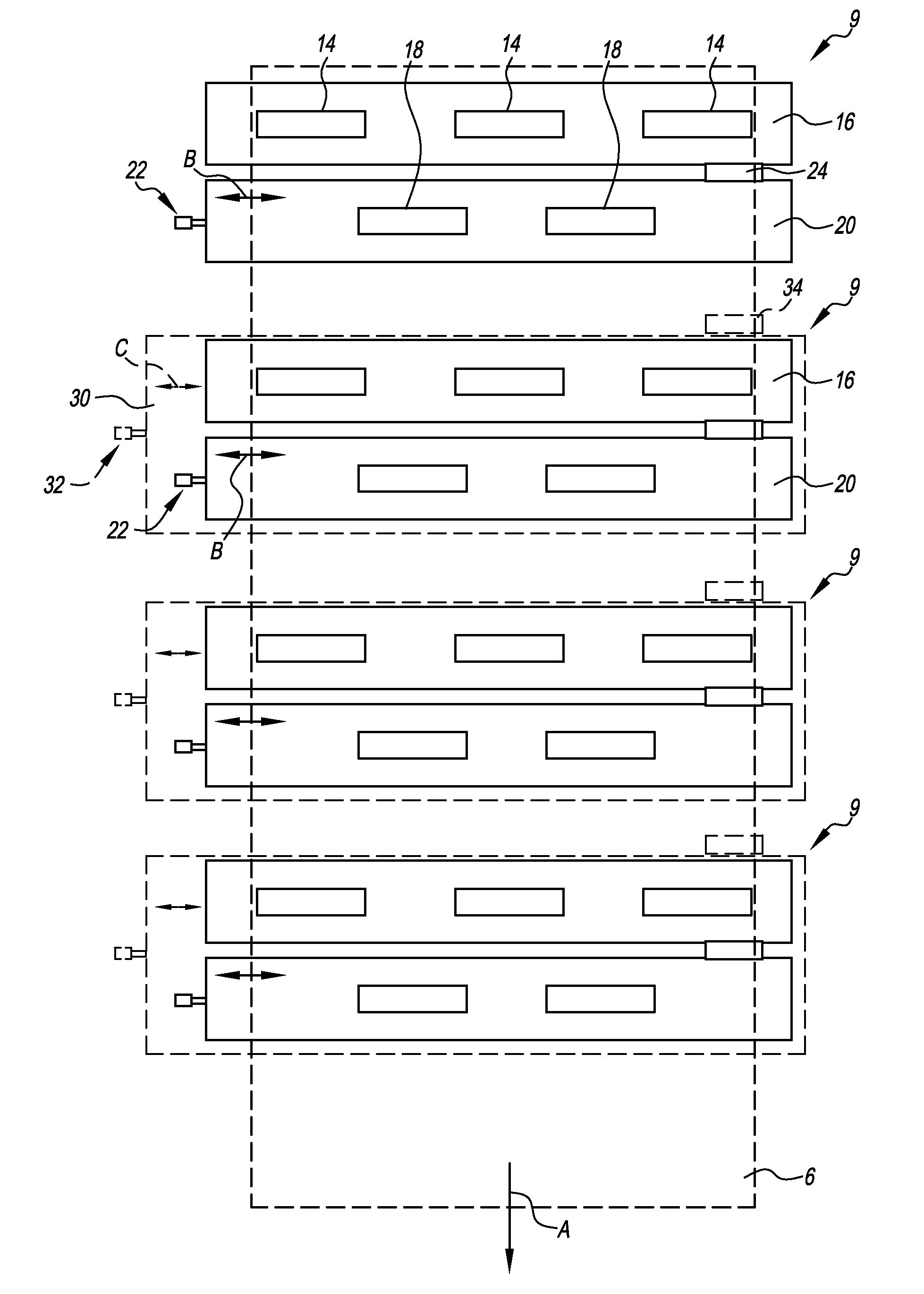
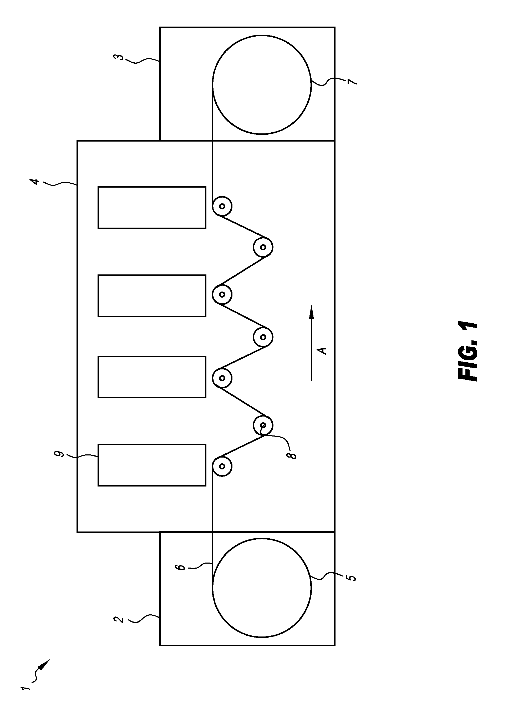
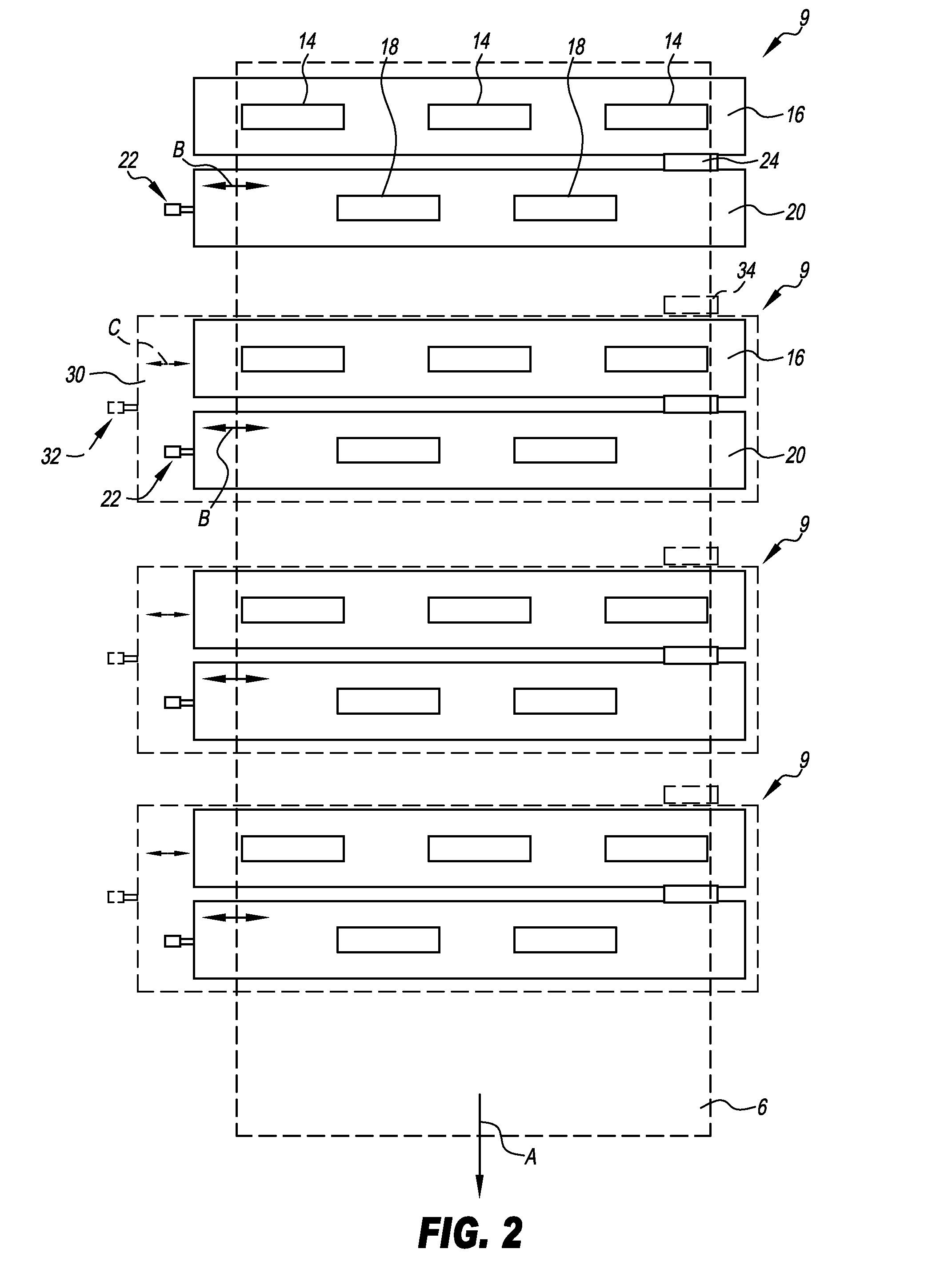
[0032]FIG. 1 is a schematic side view of a printing machine 1 without a lateral frame in order to clear the view into the inside of the printing machine 1. The printing machine 1 comprises a feeder 2, an output region 3, as well as a printing region 4 located in between. A printing substrate roll 5 is rotatably supported in the feeder 2, a printing substrate web 6 being guided from said roll through the printing region 4 to a printing substrate take-up roll 7 in the output region 3. During a printing operation, the printing substrate web 6 is conveyed from the printing substrate roll 5 to the printing substrate take-up roll 7, i.e., via a plurality of transport rollers 8 in the printing region, only a few of said transpo...


PUM


Abstract

Disclosed herein is a method for printing a printing substrate (6), in which the printing substrate (6) is printed with at least one first printing unit (9) and at least one second printing unit (9), said at least one second printing unit, viewed in a transport direction (A) of the printing substrate, being located downstream of the at least one first printing unit. In this method, a reference image is applied by the at least one first printing unit (9) and a location of the reference image is determined in a direction transverse to the transport direction of the printing substrate (6) in a position that is located, viewed in transport direction of the printing substrate, between the at least one first printing unit (9) and the at least one second printing unit (9). Subsequently, a position of the at least one second printing unit (9) transverse to the transport direction (A) of the printing substrate (6) is adjusted based on the determined location of the reference image in order to align the at least one second printing unit (9) relative to the at least one first printing unit (9) while the printing substrate (6) is being printed. In addition, a printing device (1) for printing a printing substrate (6) is described, said printing device (1) comprising at least one first printing unit (9) and at least one second printing unit (9), the at least one first printing unit (9), viewed in a transport direction (A) of the printing substrate (6), being located upstream of the at least one second printing unit (9). Furthermore, at least one sensor is provided, said sensor being aligned in a prespecified fixed positional relationship with respect to the first printing unit (9) and being directed at a position of a printing substrate path that is located, viewed in transport direction of the printing substrate, between the at least one first printing unit and the at least one second printing unit, and at least one adjustment unit is provided for the adjustment of the at least one second printing unit transverse to the transport direction (A) of the printing substrate (6) based on a signal of the at least one sensor.

Description

TECHNICAL FIELD OF THE INVENTION[0001]The present invention relates to a printing device and to a method for printing a printing substrate, comprising at least one first printing unit and at least one second printing unit, said at least first printing unit, viewed in a transport direction of the printing substrate, being located upstream of the at least one second printing unit.BACKGROUND OF THE INVENTION[0002]In printing technology, in particular in digital printing and, specifically, in ink jet printing it is known to provide a printed image with several printing units that are sequentially arranged in transport direction of a printing substrate. The printing units may, for example, be individual print lines like linear drop generators that, as an assembly, form a printhead. In so doing, the print lines are frequently arranged in groups so that, viewed in transport direction of the printing substrate, the print lines of a first group are upstream of the print lines of a second gro...

Claims


Application Information

Patent Timeline
Patent Type & Authority Applications(United States)
IPC IPC(8): B41J29/38
CPCB41J2/155
Inventor SCHLUENSS, STEFANMANDIK, ANDREASDEHN, SOENKE
Owner EASTMAN KODAK CO
Why Eureka
Try Eureka