Electronic equipment system, electronic equipment and connection equipment

a technology of electronic equipment and electronic equipment, applied in the direction of electric digital data processing, instruments, etc., to achieve the effect of effectively using the signal processing capability of electronic equipmen

Inactive Publication Date: 2012-09-13
SHARP KK
View PDF9 Cites 13 Cited by
  • Summary
  • Abstract
  • Description
  • Claims
  • Application Information

AI Technical Summary

Benefits of technology

[0008]The present invention has been made in view of the above circumstances. An object of the invention is to provide an electronic equipment system, electronic equipment and connection equipment that use si

Problems solved by technology

In the state where such devices are connected to electronic equipment, the signal lines added for USB 3.0

Method used


Image

  • Electronic equipment system, electronic equipment and connection equipment
  • Electronic equipment system, electronic equipment and connection equipment
  • Electronic equipment system, electronic equipment and connection equipment

Examples


embodiment 2

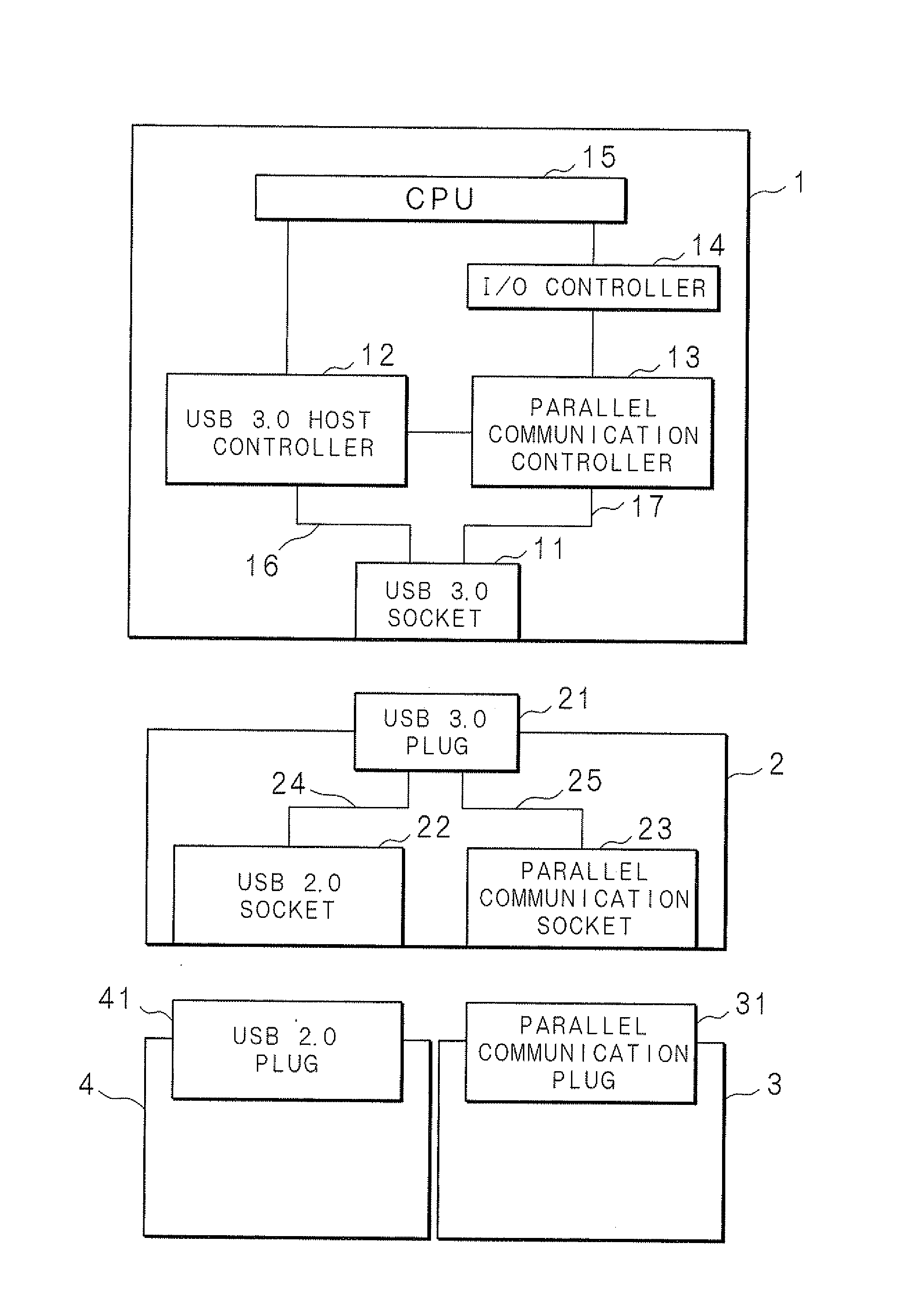
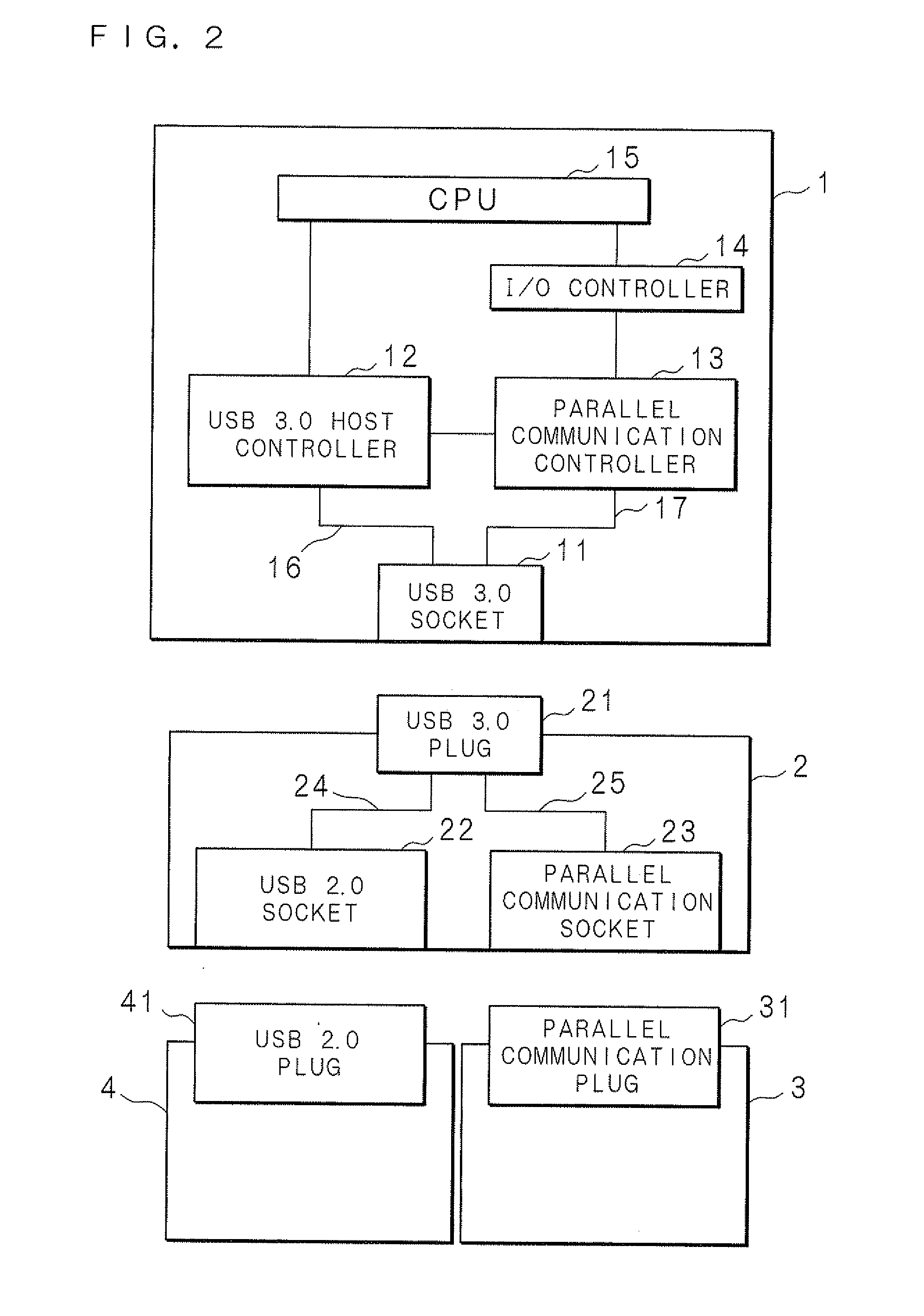
[0047]FIG. 7 is a block diagram illustrating the internal functional configuration of each of the equipment included in the electronic equipment system according to Embodiment 2. The electronic equipment 1 includes a USB 2.0 socket (fifth connector) 18 which is a connector for connecting an external device thereto. The USB 2.0 socket 18 is connected to the USB 3.0 host controller 12 by the signal lines 16. Moreover, the electronic equipment 1 includes a parallel communication socket (sixth connector) 19 for performing communication using the signal lines 17 not used for USB 2.0 instead of using the signal lines used for USB 2.0 among the signal lines for USB 3.0. The parallel communication socket 19 is connected to the parallel communication controller 13 by the signal lines 17.

[0048]The USB 2.0 socket 18 can be connected to the connection device 4 provided with the USB 2.0 plug 41. In the state where the connection device 4 is connected to the USB 2.0 socket 18, data is input from ...

embodiment 3

[0052]FIG. 8 is a block diagram illustrating the internal functional configuration of each of the equipment included in the electronic equipment system according to Embodiment 3. In Embodiment 3, the parallel communication socket 19 included in the electronic equipment 1 is a connector for connection to a device arranged inside the electronic equipment 1. The electronic equipment 1 includes an internal device 6 having a parallel communication plug 61, the internal device 6 being connected to the parallel communication socket 19 by the parallel communication plug 61. The internal device 6 is, for example, a HDD. As the other configuration parts in the electronic equipment system are similar to those in Embodiment 2, corresponding parts are denoted by the same reference codes and will not be described here.

[0053]In the state where the USB 2.0 socket 18 is connected to the connection device 4, the electronic equipment 1 and connection device 4 input / output data by processing similar to...


PUM


Abstract

A branching device (connection equipment) 2 for connection to electronic equipment 1 divides signal lines used for USB 3.0 (first interface) into signal lines used for USB 2.0 (second interface) and signal lines not used for USB 2.0. The branching device 2 can be connected to a connection device 4 performing communication in accordance with USB 2.0 and to a connection device 3 performing communication using the signal lines not used for USB 2.0. The electronic equipment 1 inputs/outputs data, through the branching unit 2, to/from the connection device 4 in accordance with USB 2.0 and to/from the connection device 3 by communication using the signal lines not used for USB 2.0. The two types of data input/output can be executed in parallel.

Description

CROSS-REFERENCE TO RELATED APPLICATIONS[0001]This Nonprovisional application claims priority under 35 U.S.C. §119(a) on Patent Application No. 2011-54580 filed in Japan on Mar. 11, 2011, the entire contents of which are hereby incorporated by reference.BACKGROUND[0002]1. Technical Field[0003]The present invention relates to an electronic equipment system including electronic equipment and connection equipment for connection to the electronic equipment, and also relates to the electronic equipment and the connection equipment.[0004]2. Description of Related Art[0005]Electronic equipment such as a notebook PC (Personal Computer) is often provided with a connection interface for connecting another device such as a mouse or hard disk drive to the electronic equipment. By connecting the device with electric equipment, the electric equipment can input / output data to / from the device and can use the function of the device. An example of such a connection interface includes a USB (Universal ...

Claims


Application Information

Patent Timeline
IPC IPC(8): G06F13/42
CPCG06F13/38G06F13/4022G06F2213/0042
Inventor OHASHI, KEI
Owner SHARP KK
Why Eureka
Try Eureka