
Larynx tube and method for the production thereof

a technology of larynx tube and larynx tube, which is applied in the direction of tracheal tube, lamination apparatus, respirator, etc., can solve the problem of not being used at all, and achieve the effect of incorrect positioning

Active Publication Date: 2012-09-20
VBM MEDIZINTECHN
View PDF8 Cites 9 Cited by
  • Summary
  • Abstract
  • Description
  • Claims
  • Application Information

AI Technical Summary

Benefits of technology

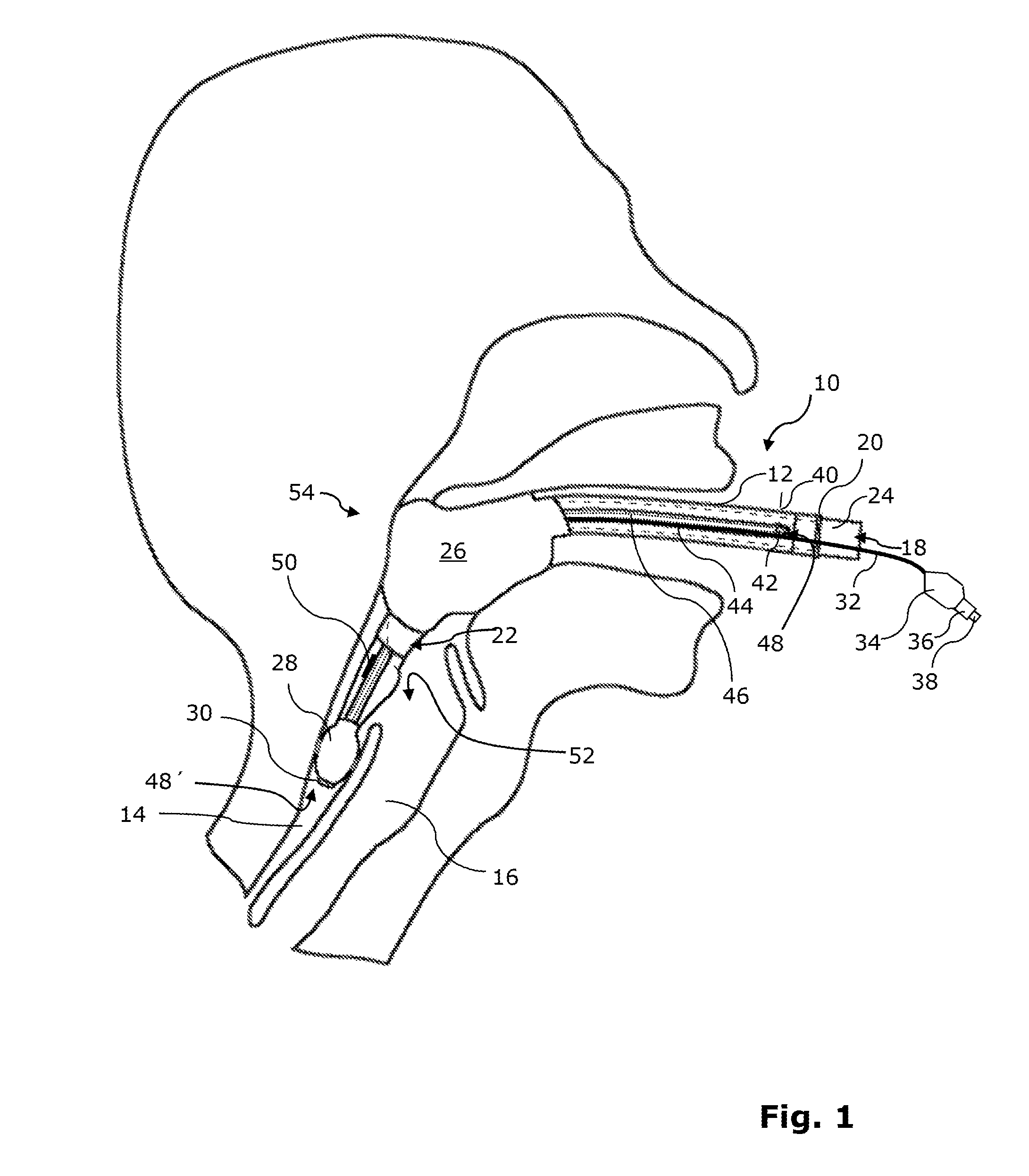
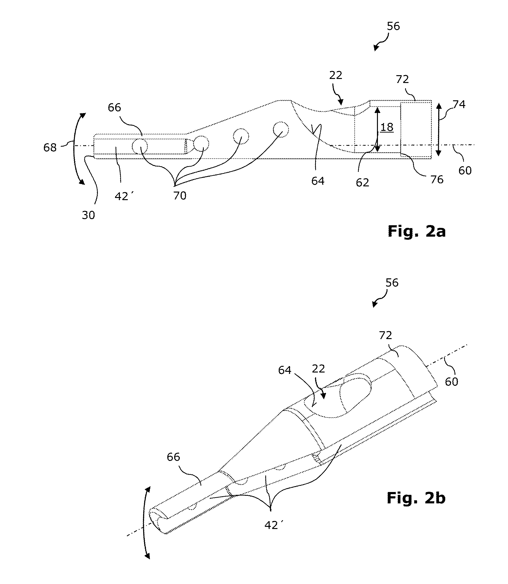
[0010]In the larynx tube according to the invention, the ventilation lumen is no longer narrowed by the drainage channel. It is thereby possible to push medical instruments, such as, for example, a bronchoscope or a suction catheter or so-called tube changers, in a simplified manner along the ventilation lumen and optionally introduce them into the trachea of a person. In particular, an endotracheal tube can also be positioned blind or with fibreoptic control (for example, by means of a bronchoscope) via the ventilation lumen of the larynx tube in the trachea of a person in order to thus achieve definitive protection of the airway. The larynx tube does not have to be removed for this, so that sufficient oxygen supply can be ensured for the person at all times. Owing to the fact that the drainage tube is arranged in a longitudinal groove of the tube shaft, the larynx tube with a (still) compact overall construction can be inserted into the pharynx (gullet) of a person in a simple manner involving little trauma. With regard to opening the jaws of a person required for the introduction of the larynx tube, the drainage tube may in particular be arranged at a lateral wall region of the tube shaft. Owing to the arrangement of the drainage channel in the longitudinal groove, it is further possible to produce a connection of the drainage tube to the tube shaft that is particularly robust and resistant to bending and shearing forces to which the larynx tube is subjected in practice. The ventilation lumen of the tube shaft may advantageously have a circular opening cross-section so that bronchoscopes and endotracheal tubes which are used in practice can be pushed through the ventilation lumen in a simplified manner.
[0021]In a particularly preferred manner, the wall reinforcement elements at least partially form groove flanks of the longitudinal groove of the tube shaft. The wall reinforcement elements are thereby pulled forward from the tube shaft laterally in the direction towards the drainage channel so far that the drainage pipe can also be protected against the consequences of possibly being bitten on or bitten through.

Problems solved by technology

However, with commercially available larynx tubes, the drainage channel narrows the ventilation lumen in such a manner that medical instruments or auxiliary means, such as bronchoscopes, can pass the ventilation lumen only with difficulty or not at all.

Method used


Image

  • Larynx tube and method for the production thereof
  • Larynx tube and method for the production thereof
  • Larynx tube and method for the production thereof

Examples


Embodiment Construction

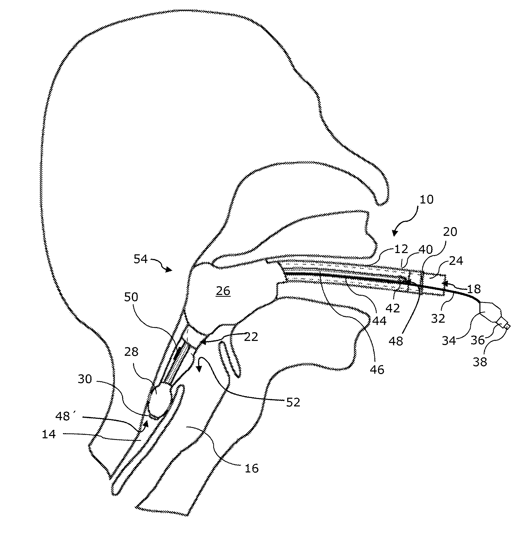
[0032]FIG. 1 is a side view of a larynx tube 10 according to the invention. The larynx tube 10 comprises a tube shaft 12 which has an angled longitudinal profile. The angled longitudinal profile ensures that the larynx tube 10 can be inserted into the oesophagus 14 of a person in a simple and non-traumatic manner and it is not incorrectly inserted into the trachea (windpipe) 16.

[0033]The tube shaft 12 has a single ventilation lumen 18 which is illustrated in the Figures with broken lines. The ventilation lumen 18 extends from the proximal end 20 of the tube shaft 12 as far as a lateral ventilation opening 22 which is arranged in the wall of the tube shaft 12.

[0034]At the proximal end 20 of the tube shaft 12 there is arranged a connection piece 24 for the connection of a ventilation bag which is not illustrated in greater detail in the drawings, or a ventilation device.

[0035]In a manner known per se, the tube shaft 12 has two inflatable cuffs 26, 28, that is to say, block collars whi...


PUM

PropertyMeasurementUnit
Symmetryaaaaaaaaaa

Abstract

A larynx tube (10) for ventilation has a tube shaft (12), which has a ventilation lumen (18), having an oesophageal cuff (28) which is arranged on the tube shaft (12) for blocking the oesophagus (14) and having a drainage channel (46) which has a drainage opening (48′) which is arranged distally in respect of the oesophageal cuff (28). The drainage channel (46) is formed by a drainage pipe (44) which is arranged in a longitudinal groove (42) of the tube shaft (12) which is provided on an outer side (40) of the tube shaft (12). The drainage pipe (44) is adhesively bonded and / or welded to the tube shaft (12). The tube shaft (12) has a proximal and a distal longitudinal shaft portion (56, 58) which are adhesively bonded and / or welded to each other. The distal longitudinal shaft portion (58) is constructed as an injection-moulded component.

Description

[0001]This application claims Paris Convention priority of DE 10 2011 001 325.3 filed Mar. 16, 2011 the complete disclosure of which is hereby incorporated by reference.BACKGROUND OF THE INVENTION[0002]The invention relates to a larynx tube and a method for the production thereof.[0003]Acting as supraglottal respiratory tracts, larynx tubes have become established in recent years as indispensable means for temporarily protecting the airway and are used both for spontaneous respiration and positive pressure ventilation.[0004]Larynx tubes which are commercially available have a tube shaft having a ventilation lumen. There is arranged on the tube shaft an inflatable oesophageal cuff, that is to say, an inflatable blocking collar for blocking the oesophagus, and a pharyngeal cuff for blocking the pharynx. A ventilation opening of the ventilation lumen is arranged between the two cuffs.[0005]In order to protect the airway, the larynx tube is introduced from the mouth into the pharynx unt...

Claims


Application Information

Patent Timeline
IPC IPC(8): A61M16/04B32B37/12
CPCA61M16/04A61M16/0488A61M2205/32A61M16/0493A61M16/0409A61M16/0415A61M16/0459A61M2207/00A61M16/0443A61M16/0477
Inventor BERTRAM, VOLKER
Owner VBM MEDIZINTECHN
Learn More