Alky-one gasket

a gasket and alkyl-one technology, applied in the direction of engine seals, flanged joints, pipe joints, etc., can solve the problems of high minimum seating, alternating layers of filler and metal, high cost, etc., and achieve the effect of decreasing thickness

Inactive Publication Date: 2012-09-20
ADVANCED SEALING & SUPPLY COMPANY
View PDF17 Cites 27 Cited by
  • Summary
  • Abstract
  • Description
  • Claims
  • Application Information

AI Technical Summary

Benefits of technology

[0022]The presently preferred embodiment of the invention has been found to exhibit a low leakage rate, i.e., approximately 1 ppm, when compared to conventional spiral wound gaskets which have been found to have much higher leakage rates, i.e., approximately 500 ppm.

Problems solved by technology

This results in alternating layers of filler and metal.
Such gaskets have proven to be reliable in most applications, and allow lower clamping forces than solid gaskets, albeit with higher costs.
During hotter periods, the Teflon inner rings, which may require a relatively high minimum seating stress (i.e., 15,000 psi), can severely distort or cup.
Spiral wound versions of such gaskets are also susceptible to breakage of the sealing element in response to over compression.
Spiral wound gaskets have also been noted to have a relatively high leakage rate (e.g., 500 ppm), which is problematic in severe acid service applications.
Additionally, Teflon filler materials used in spiral wound gaskets are not fire safe.

Method used


Image

  • Alky-one gasket
  • Alky-one gasket
  • Alky-one gasket

Examples


Embodiment Construction

[0025]The description below sets forth the presently preferred embodiment of the invention in relation to the described application. It is to be understood, however, that various other embodiments of the invention may be implemented for the described application, and other applications, without departing from the broader aspects of the present invention.

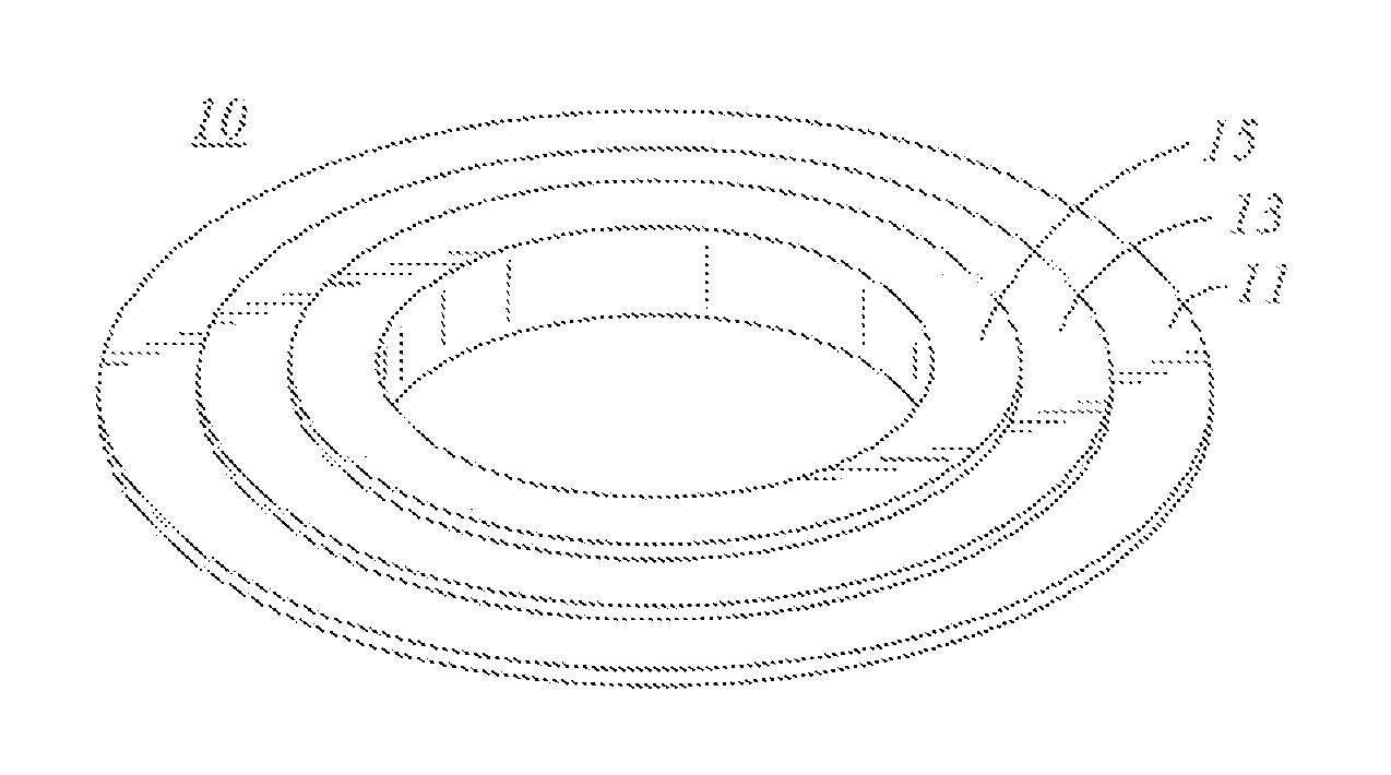
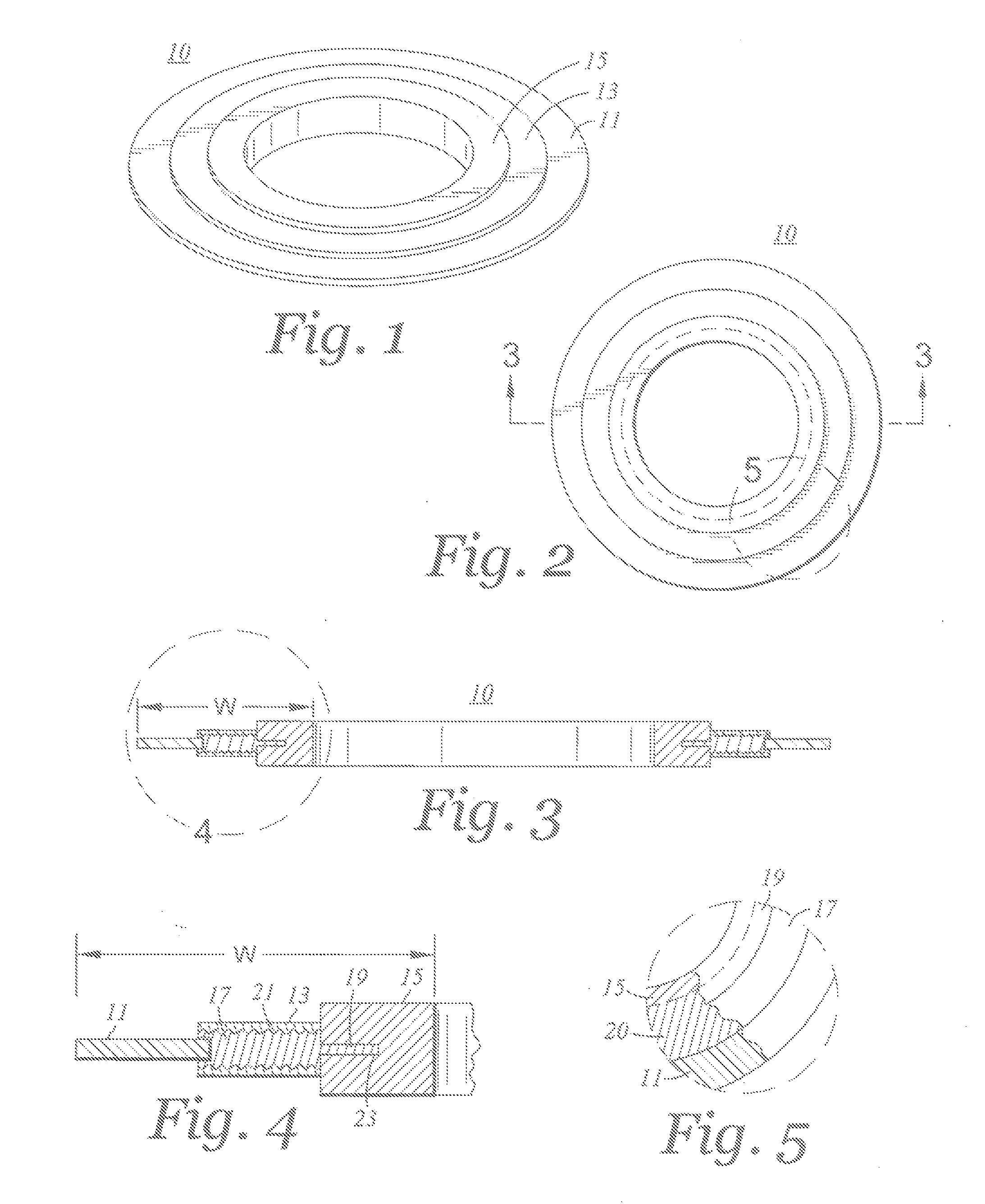
[0026]Referring to the drawings, the presently preferred embodiment of fluid sealing gasket 10 is illustrated. As shown in FIG. 1, the exterior surfaces of gasket 10 define an outer guide ring 11, serrated core profile sealing element 13 and inner barrier pillow 15. The serrated profile sealing core facing 13 and the inner barrier pillow 15 define a pair of fluid seals which, upon compression and normal use, provides an acid barrier and a fluid tight seal for the sealing gasket 10.

[0027]The interior construction of the gasket 10 is illustrated at FIGS. 3, 4, and 5. Referring to FIGS. 3 and 4, outer guide ring 11 is shown extending in...


PUM


Abstract

A fluid sealing gasket is provided which comprises an outer guide ring, a serrated profile sealing element engaged to the outer guide ring and extending radially inward therefrom and an inner attachment ring engaged to the serrated profile sealing element and extending radially inward therefrom. An inner barrier pillow is formed about the inner attachment ring and extends radially inwardly therefrom. A graphite sealing element facing is formed about the serrated profile core, the serrated profile sealing element facing being disposed in abutting contact with the inner barrier pillow.

Description

CROSS-REFERENCE TO RELATED APPLICATIONS[0001]Not ApplicableSTATEMENT RE: FEDERALLY SPONSORED RESEARCH / DEVELOPMENT[0002]Not ApplicableBACKGROUND[0003]The present invention is directed to a gasket design for fluid sealing in severe acid environments, e.g., in alkalization plants.[0004]Sealing gaskets have been used in a variety of different applications. The construction of such gaskets is typically a function of the application, the environment in which the gaskets are to be utilized, and other factors. Where gaskets are intended to be used in severe acid service environments the gasket constructions have included spiral wound gaskets incorporating carbon steel outer guide rings, windings made of Monel® and Teflon, or flexible graphite, and inner rings of Teflon, faced Teflon-coated carbon steel or Monel. Generally, the gasket winding has a metal (normally carbon rich or stainless steel) wound outwards in a circular spiral (other shapes are possible) with a filler material (generally...

Claims


Application Information

Patent Timeline
Patent Type & Authority Applications(United States)
IPC IPC(8): F16J15/02
CPCF16L23/18F16J15/122
Inventor STUBBLEFIELD, ALANREEVES, DAVID WALTER
Owner ADVANCED SEALING & SUPPLY COMPANY
Why Eureka
Try Eureka