Charging circuit

Active Publication Date: 2012-09-20
ROHM CO LTD
View PDF12 Cites 13 Cited by
  • Summary
  • Abstract
  • Description
  • Claims
  • Application Information

AI Technical Summary

Benefits of technology

[0011]The present invention has been made in order to solve such a problem. Accordingly, it is an exemplary purpose of an embodiment of the present invention to provide a charging circuit which is capable of charging a secondary battery with high efficiency.

Problems solved by technology

In some cases, this leads to a problem in that the charging circuit cannot operate normally.
Furthermore, such a solar battery requires wiring space in order to connect the adjacent cells, leading to a problem of a reduced aperture ratio, and also to deterioration in its appearance.
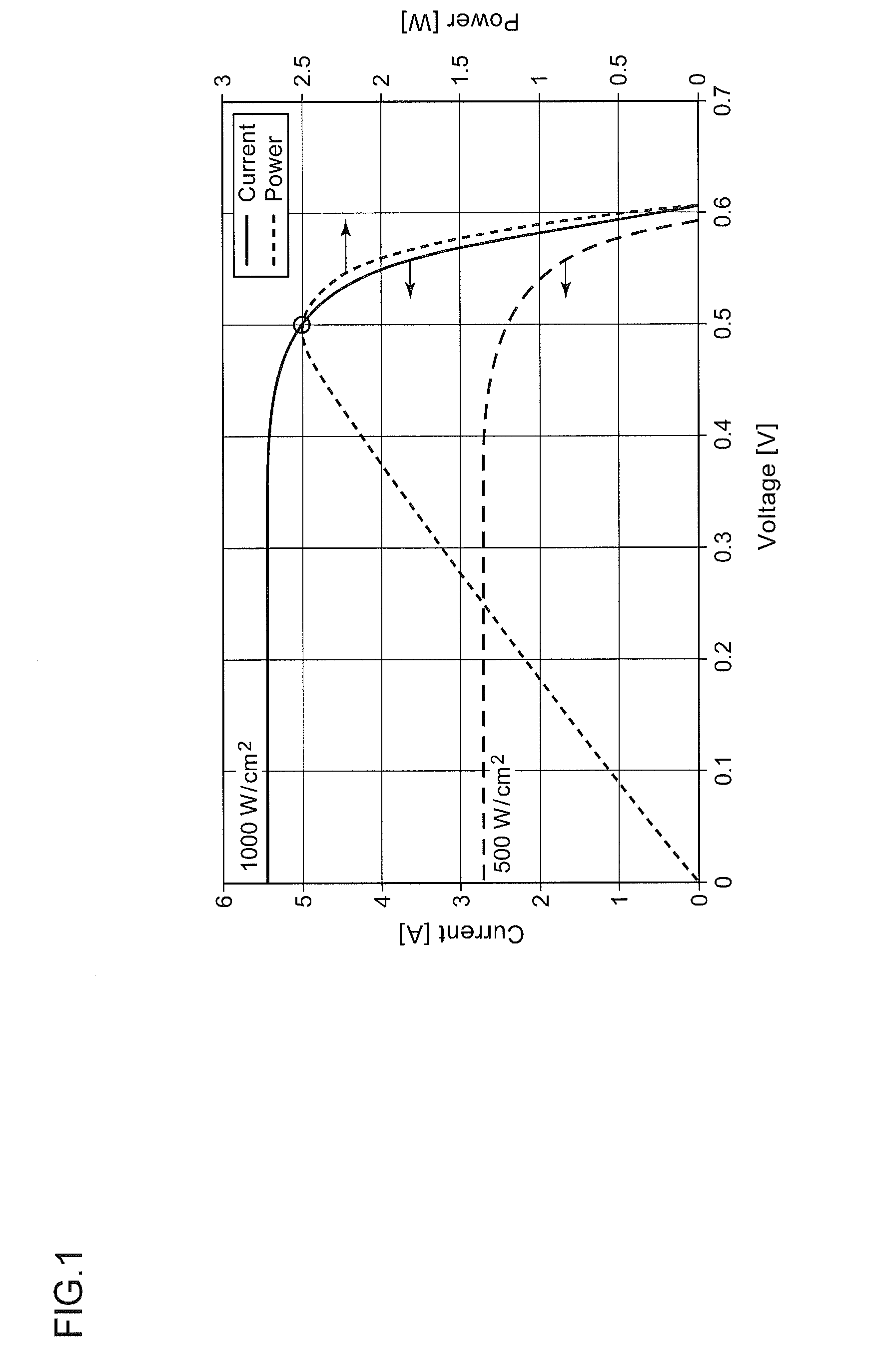
Accordingly, in a case in which feedback control is applied to such a DC / DC converter such that the input voltage approaches 0.5 V regardless of the illumination intensity, such a solar battery does not necessarily provide its maximum power.
This leads to a problem of a complicated circuit configuration.
Furthermore, with the MPP method, the electric power supplied to such a secondary battery that acts as a load of the DC / DC converter does not necessarily reach its maximum even if the output voltage of the solar battery, i.e., the input voltage of the DC / DC converter is set to its maximum.
This is because electric power is consumed by the DC / DC converter itself.

Method used


Image

  • Charging circuit
  • Charging circuit
  • Charging circuit

Examples


Embodiment Construction

[0055]The invention will now be described based on preferred embodiments which do not intend to limit the scope of the present invention but exemplify the invention. All of the features and the combinations thereof described in the embodiment are not necessarily essential to the invention.

[0056]In the present specification, the state represented by the phrase “the member A is connected to the member B” includes a state in which the member A is indirectly connected to the member B via another member that does not substantially affect the electric connection therebetween, or that does not damage the functions or effects of the connection therebetween, in addition to a state in which the member A is physically and directly connected to the member B.

[0057]Similarly, the state represented by the phrase “the member C is provided between the member A and the member B” includes a state in which the member A is indirectly connected to the member C, or the member B is indirectly connected to ...


PUM


Abstract

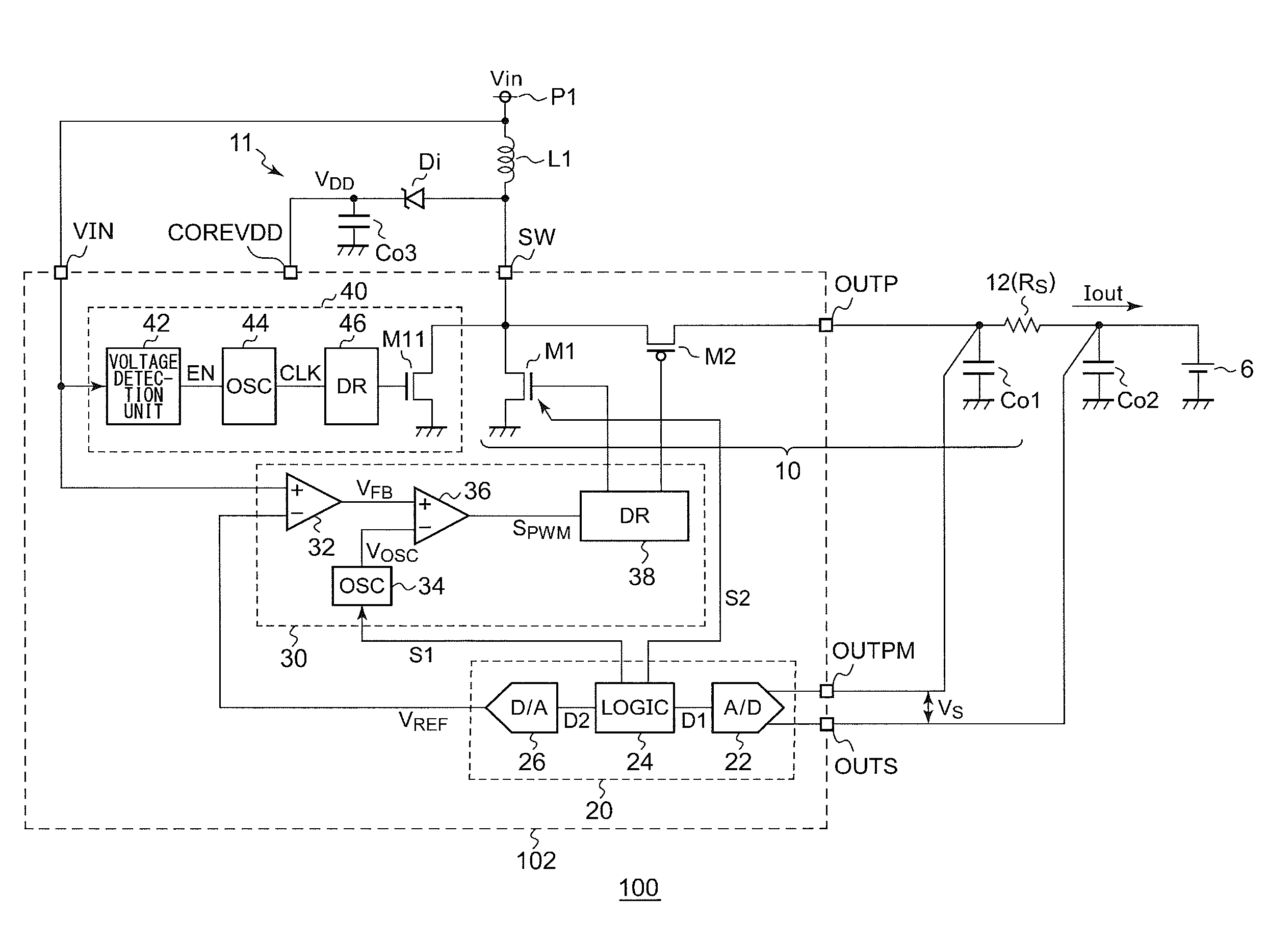
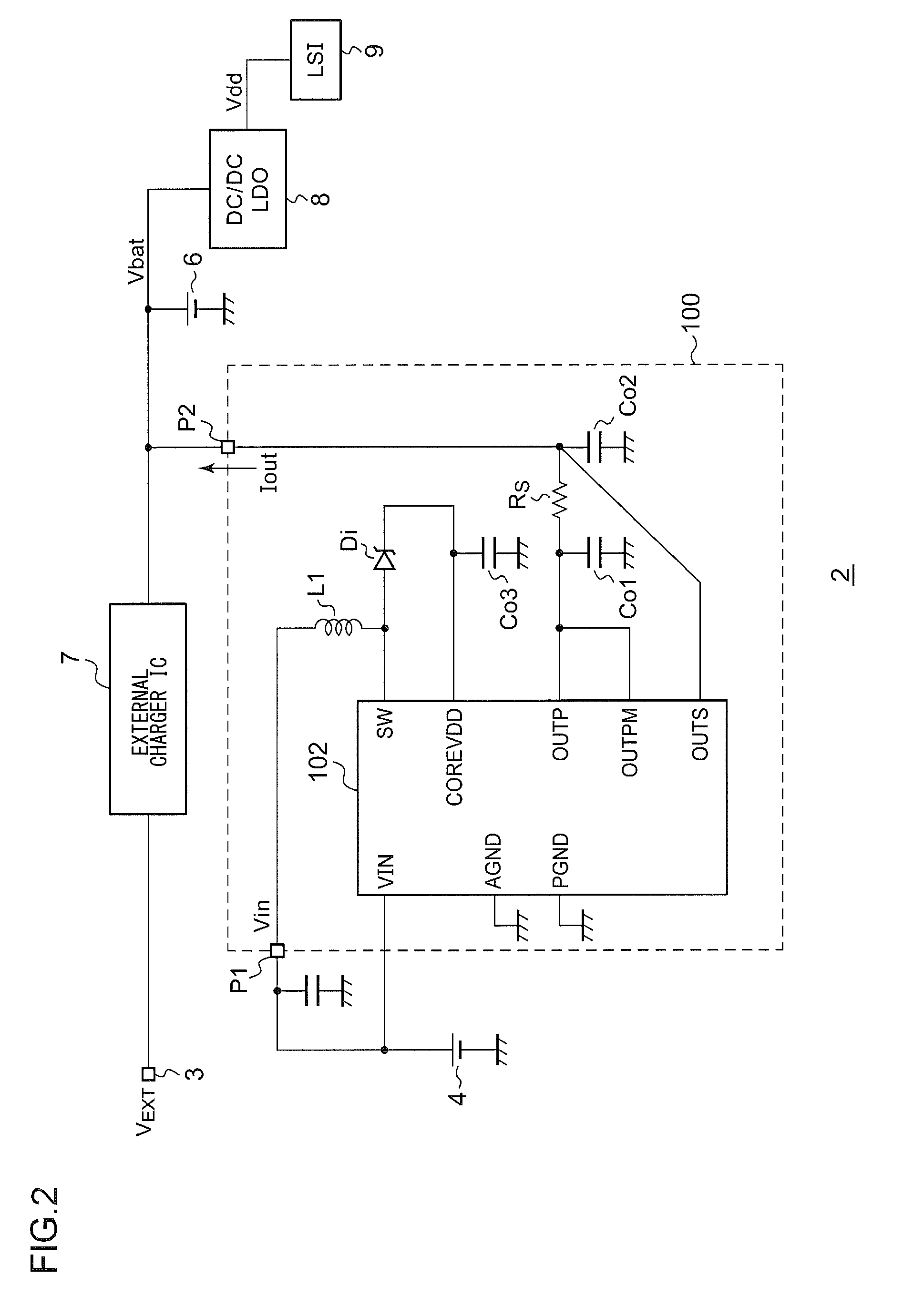
A charging circuit receives electric power from a solar battery, and charges a secondary battery. A charging current detection unit generates a detection signal that corresponds to a charging current supplied from a DC / DC converter to the secondary battery. A control circuit generates a reference voltage that corresponds to the detection signal. A driving unit generates a pulse signal having a duty ratio that is adjusted such that the voltage output from the solar battery matches the reference voltage, and performs switching of a switching transistor according to the pulse signal. A control circuit adjusts the reference voltage such that the reference voltage becomes greater.

Description

BACKGROUND OF THE INVENTION[0001]1. Field of the Invention[0002]The present invention relates to a charging circuit configured to charge a secondary battery using electric power received from a solar battery.[0003]2. Description of the Related Art[0004]In recent years, electronic devices such as cellular phones, PDAs (Personal Digital Assistants), and laptop personal computers, mount a secondary battery. At present, such a secondary battery is charged using electric power received from an adapter configured to convert a commercial AC voltage into a DC voltage, or electric power received from a USB bus. In recent years, there have been efforts to provide an electronic device configured to mount a solar battery, and to charge such a secondary battery using electric power received from such a solar battery.[0005]In a case in which such a solar battery to be used to charge such a secondary battery has a multi-cell structure in which multiple battery cells are stacked, e.g., a structure ...

Claims


Application Information

Patent Timeline
IPC IPC(8): H02J7/00
CPCH01M10/44H01M10/465Y02E10/566H02J7/35H02J7/045Y02E10/56Y02E60/10H02J7/04H02J7/00714H02J7/007182
Inventor ISHINO, TSUTOMUSAKAMOTO, TADAYUKI
Owner ROHM CO LTD
Why Eureka
Try Eureka