Battery life indication techniques for an electronic device

a technology for electronic devices and battery life, applied in the direction of instruments, electrochemical generators, alarms, etc., can solve the problems of inability to utilize all of the energy stored in the battery, prone to voltage drop, and sharp voltage drop at the end of li

Active Publication Date: 2012-09-20
MEDTRONIC MIMIMED INC
View PDF11 Cites 54 Cited by
  • Summary
  • Abstract
  • Description
  • Claims
  • Application Information

AI Technical Summary

Benefits of technology

A battery monitoring system has been developed for devices with both main and backup batteries. It consists of a voltage sensor, a control module, a timer, and a battery level indication. By measuring the voltage of the main battery and tracking its usage through different power phases, the system can estimate how much battery life remains. This allows users to better manage their electronics' energy consumption and avoid unexpected battery failures.

Problems solved by technology

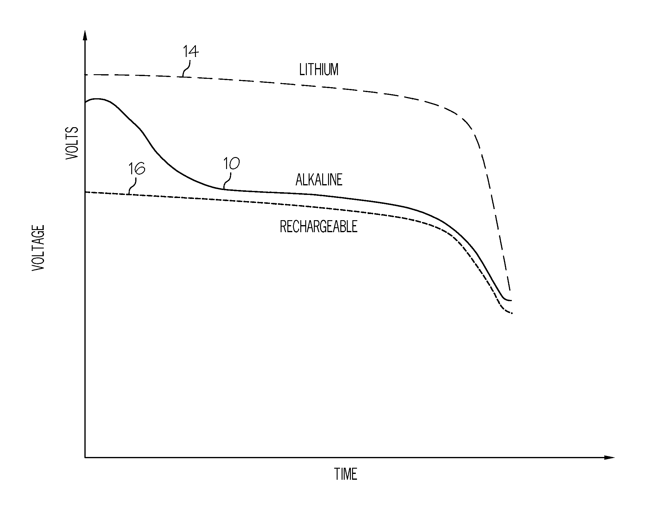
The technical problem addressed in this patent is the inaccuracy and imprecision of conventional battery life indicators used with electronic devices. These indicators often do not use a proportional time scale to represent the remaining amount of battery life, which can be confusing for users. The patent aims to provide a battery life indicator that accurately and proportionately indicates the remaining amount of battery life relative to actual runtime of the battery.

Method used


Image

  • Battery life indication techniques for an electronic device
  • Battery life indication techniques for an electronic device
  • Battery life indication techniques for an electronic device

Examples


Embodiment Construction

[0020]The following detailed description is merely illustrative in nature and is not intended to limit the embodiments of the subject matter or the application and uses of such embodiments. As used herein, the word “exemplary” means “serving as an example, instance, or illustration.” Any implementation described herein as exemplary is not necessarily to be construed as preferred or advantageous over other implementations. Furthermore, there is no intention to be bound by any expressed or implied theory presented in the preceding technical field, background, brief summary or the following detailed description.

[0021]Techniques and technologies may be described herein in terms of functional and / or logical block components, and with reference to symbolic representations of operations, processing tasks, and functions that may be performed by various computing components or devices. It should be appreciated that the various block components shown in the figures may be realized by any numb...


PUM


Abstract

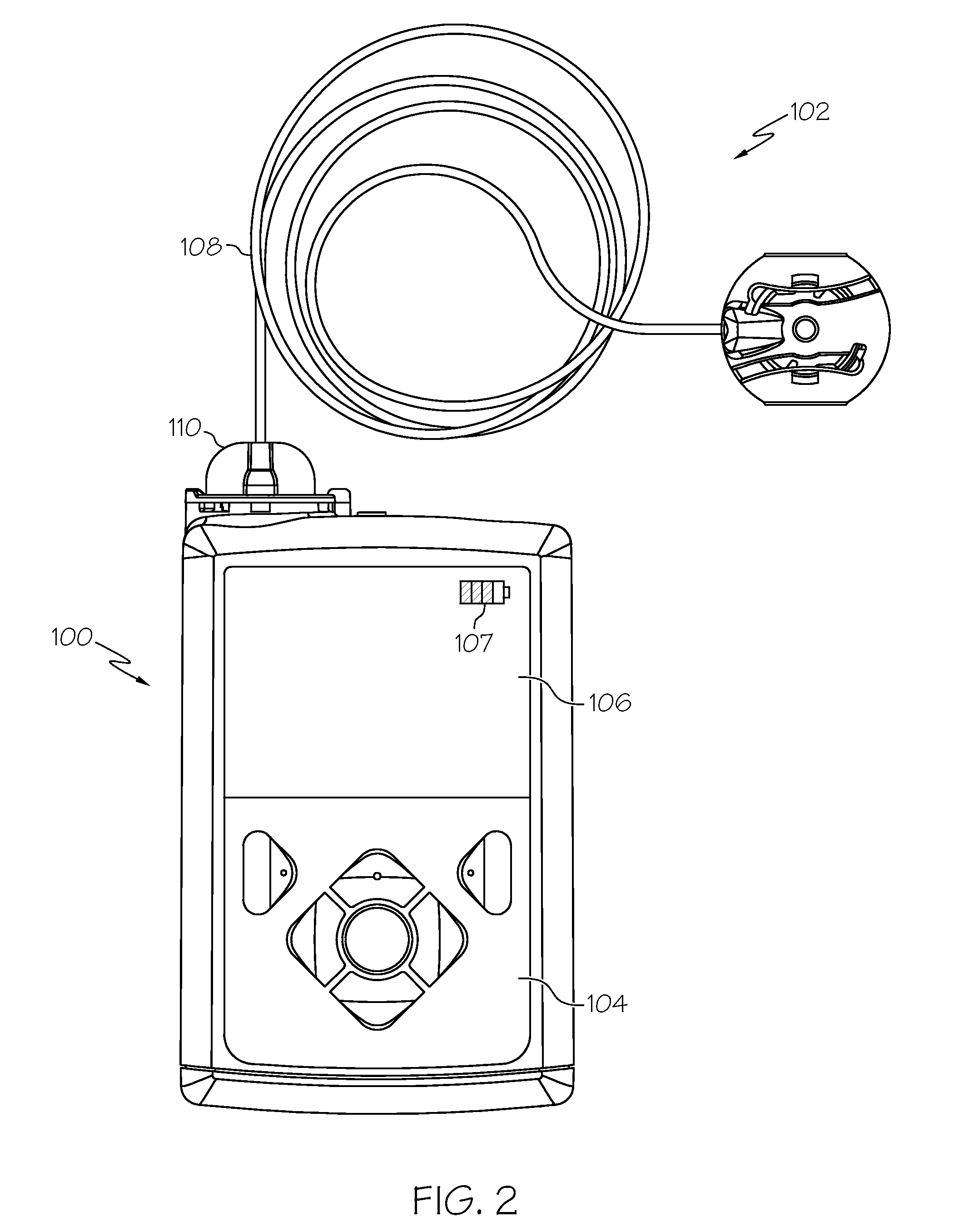
A portable electronic device, such as a fluid infusion device, obtains its operating power from a primary battery and a secondary battery. The primary battery may be a replaceable battery, and the secondary battery may be a rechargeable battery that can be charged with the primary battery under certain conditions. The device utilizes a power management scheme that transitions between the primary battery and/or the secondary battery to prolong the useful life of the primary battery. The device may also generate an intelligent battery life indicator that displays an accurate representation of the remaining life of the primary battery.

Description


Claims


Application Information

Patent Timeline
Owner MEDTRONIC MIMIMED INC
Why Eureka
Try Eureka