Meta-material MIMO antenna

a technology of metal-material mimo and antenna, which is applied in the structure of individual energised antenna arrays, resonant antennas, radiating elements, etc., can solve the problems of deterioration of receipt sensitivity, interference between antennas, and difficulty in improving isolation characteristics

Inactive Publication Date: 2012-09-20
LG INNOTEK CO LTD +1
View PDF8 Cites 9 Cited by
  • Summary
  • Abstract
  • Description
  • Claims
  • Application Information

AI Technical Summary

Benefits of technology

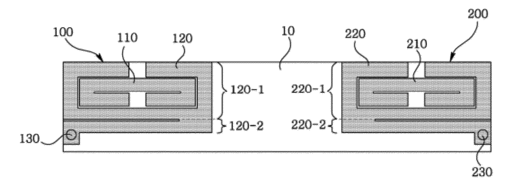
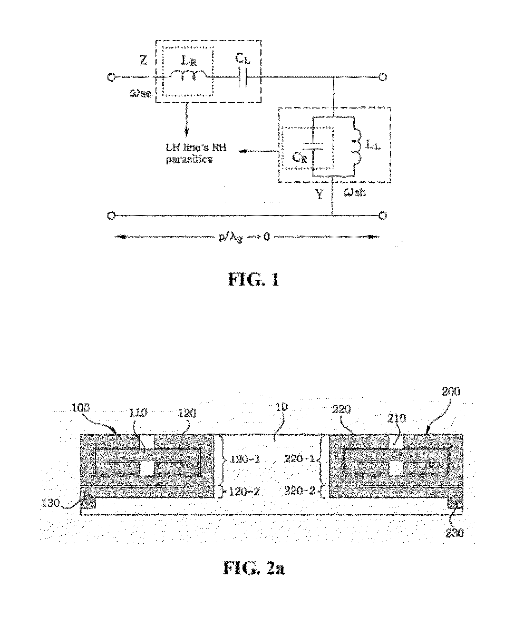
[0022]The meta-material MIMO antenna according to the present disclosure has advantageous effect in that, unlike the conventional SRR, a SRR can be formed based on CRLH (Composite Left and Right Handed) meta-material structures and can maintain an antenna characteristic as a MIMO antenna as well. Meanwhile, miniaturization of an antenna can be implemented by inducing phase shift-free meta-material characteristic based on CRLH through intervals of strips, via and coupled strips thereof. Furthermore, a miniaturized MIMO antenna can be implemented through plane mushroom-cell structured coupler removal structure controlling a current flow in realizing a multiple feeding MIMO antenna using a miniaturized antenna.

Problems solved by technology

Meanwhile, to implement a MIMO antenna system in a wireless portable terminal, two or more antenna elements should be disposed in a space smaller than half a wavelength, and thus it is difficult to improve an isolation characteristic.
Since a plurality of antennas is used in a MIMO antenna system, interference may occur between the antennas.
If two SRR resonators are present in a neighboring space, the resonators relatively cause generation of deterioration of receipt sensitivity, such that additional structure is needed to remove the deterioration of receipt sensitivity.
However, size miniaturization of antennas is disadvantageously hampered due to the structure added to remove the deterioration of receipt sensitivity.

Method used


Image

  • Meta-material MIMO antenna
  • Meta-material MIMO antenna
  • Meta-material MIMO antenna

Examples


Embodiment Construction

[0040]Hereinafter, exemplary embodiments of the present disclosure are described in detail with reference to the accompanying drawings. It will be appreciated that for simplicity and / or clarity of illustration, elements illustrated in the figure have not necessarily been drawn to scale. For example, the dimensions of some of the elements may be exaggerated relative to other elements for clarity. Further, if considered appropriate, reference numerals have been repeated among the figures to indicate corresponding and / or analogous elements.

[0041]Particular terms may be defined to describe the disclosure in the best mode as known by the inventors. Accordingly, the meaning of specific terms or words used in the specification and the claims should not be limited to the literal or commonly employed sense, but should be construed in accordance with the spirit and scope of the disclosure. The definitions of these terms therefore may be determined based on the contents throughout the specific...


PUM


Abstract

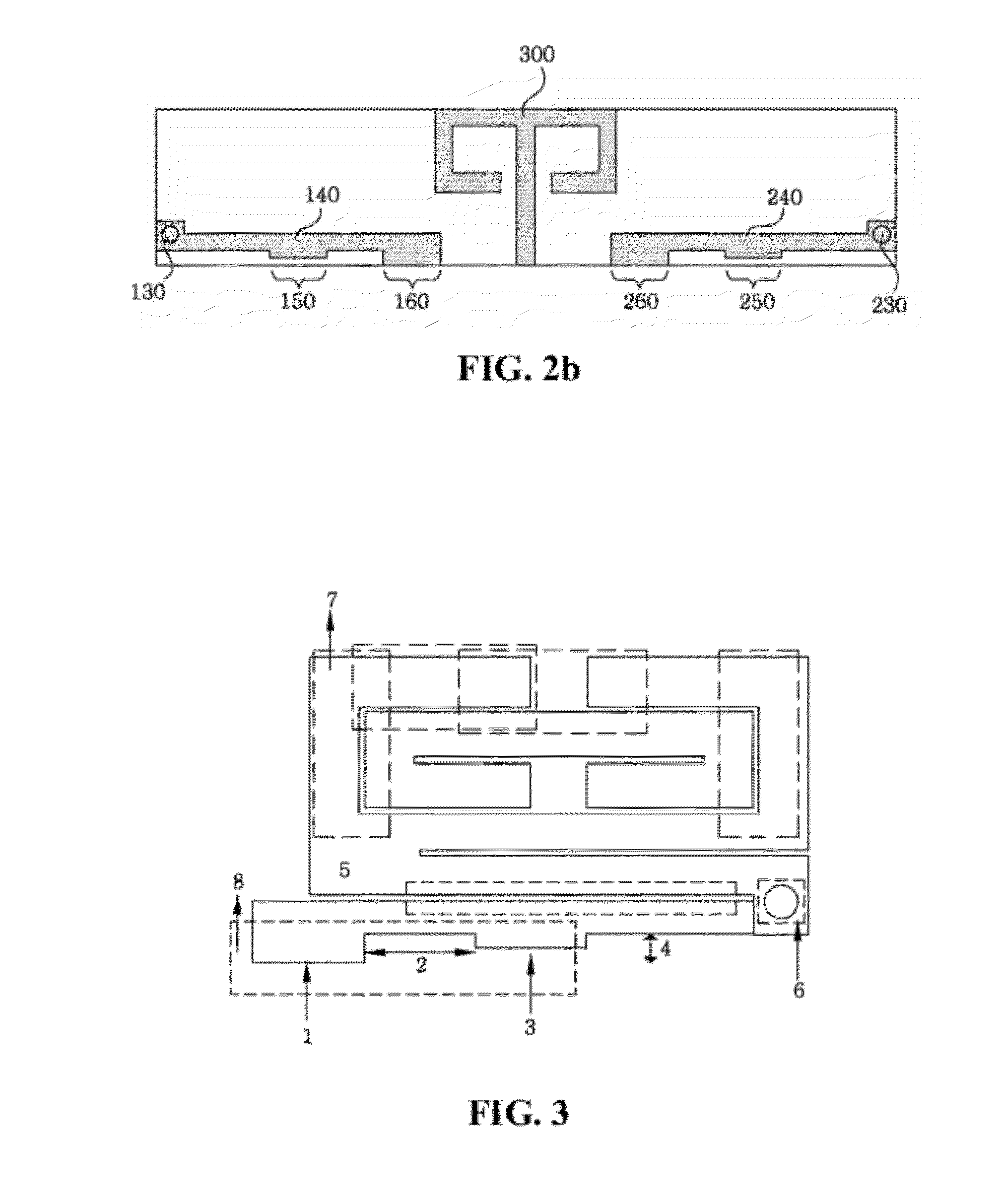
A meta-material MIMO antenna is disclosed, wherein the meta-material MIMO antenna includes a substrate; a first top radiator formed at one side of top surface of the substrate, and including an inner radiator and an outer radiator discrete from the inner radiator to encompass the inner radiator from outside; a second top radiator symmetrically formed against the first top radiator and formed on the other side of the top surface of the substrate; a first bottom radiator electrically connected to the first top radiator and formed on one side of bottom surface of the substrate; a second bottom radiator symmetrically formed against the first bottom radiator and formed on the other side of the bottom surface of the substrate; and a coupler remover interposed between the first and second bottom radiators, whereby the antenna can be miniaturized to enhance a high isolation.

Description

CROSS-REFERENCE TO RELATED APPLICATION[0001]This application claims the benefit under 35 U.S.C. §119 of Korean Patent Application No. 10-2011-0022358, filed Mar. 14, 2011, which is hereby incorporated by reference in its entirety.BACKGROUND OF THE INVENTION[0002]1. Field of the Invention[0003]Exemplary embodiments of the present disclosure may relate to a meta-material MIMO (Multiple Input Multiple Output) antenna, and more particularly to a super small MIMO antenna interpolated by a meta-material structured SRR (Split Ring Resonator) radiator and a new coupler-removal structure.[0004]2. Description of Related Art[0005]An antenna has been gradually miniaturized and its structure has been also variably changed. Particularly, function of an antenna enabling wireless communication has been greatly enlarged due to rapid development of communication technologies, and miniaturization of wireless communication devices thus requires miniaturization of antenna size. Therefore, MIMO technolog...

Claims


Application Information

Patent Timeline
Patent Type & Authority Applications(United States)
IPC IPC(8): H01Q1/36
CPCH01Q1/38H01Q1/36H01Q1/24H01Q21/08H01Q21/30
Inventor KIM, JONGGUKCHO, JEONGHOONKAHNG, SUNGTEKKU, JAKWONKIM, KYUNGSUKJANG, GEONHOYOO, SEONGRYONG
Owner LG INNOTEK CO LTD
Why Eureka
Try Eureka