Display Device with Integrated Photovoltaic Cells, with Improved Luminosity

Active Publication Date: 2012-09-20
GARMIN
View PDF7 Cites 52 Cited by
  • Summary
  • Abstract
  • Description
  • Claims
  • Application Information

AI Technical Summary

Benefits of technology

[0023]In a general manner, to at least partly eliminate the reflection of the ambient light on the surface of the photovoltaic plate, the latter may comprise at least one antireflection layer. Here, this term enc

Problems solved by technology

This same document comprises another embodiment in which the back-illumination light is focused in the space between the photocells by a lens situated between the back-illumination light source and the substrate on which the array of pixels is located; this embodiment presents the drawback of requiring extremely precise position

Method used


Image

  • Display Device with Integrated Photovoltaic Cells, with Improved Luminosity
  • Display Device with Integrated Photovoltaic Cells, with Improved Luminosity
  • Display Device with Integrated Photovoltaic Cells, with Improved Luminosity

Examples


Example

[0035]Further areas of applicability of the present disclosure will become apparent from the detailed description provided hereinafter. It should be understood that the detailed description of exemplary embodiments are intended for illustration purposes only and are, therefore, not intended to necessarily limit the scope of the disclosure.

DETAILED DESCRIPTION OF THE INVENTION

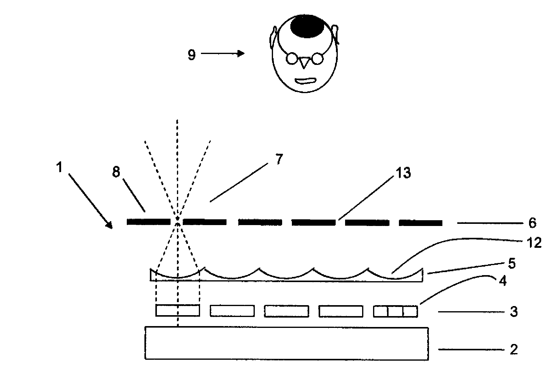
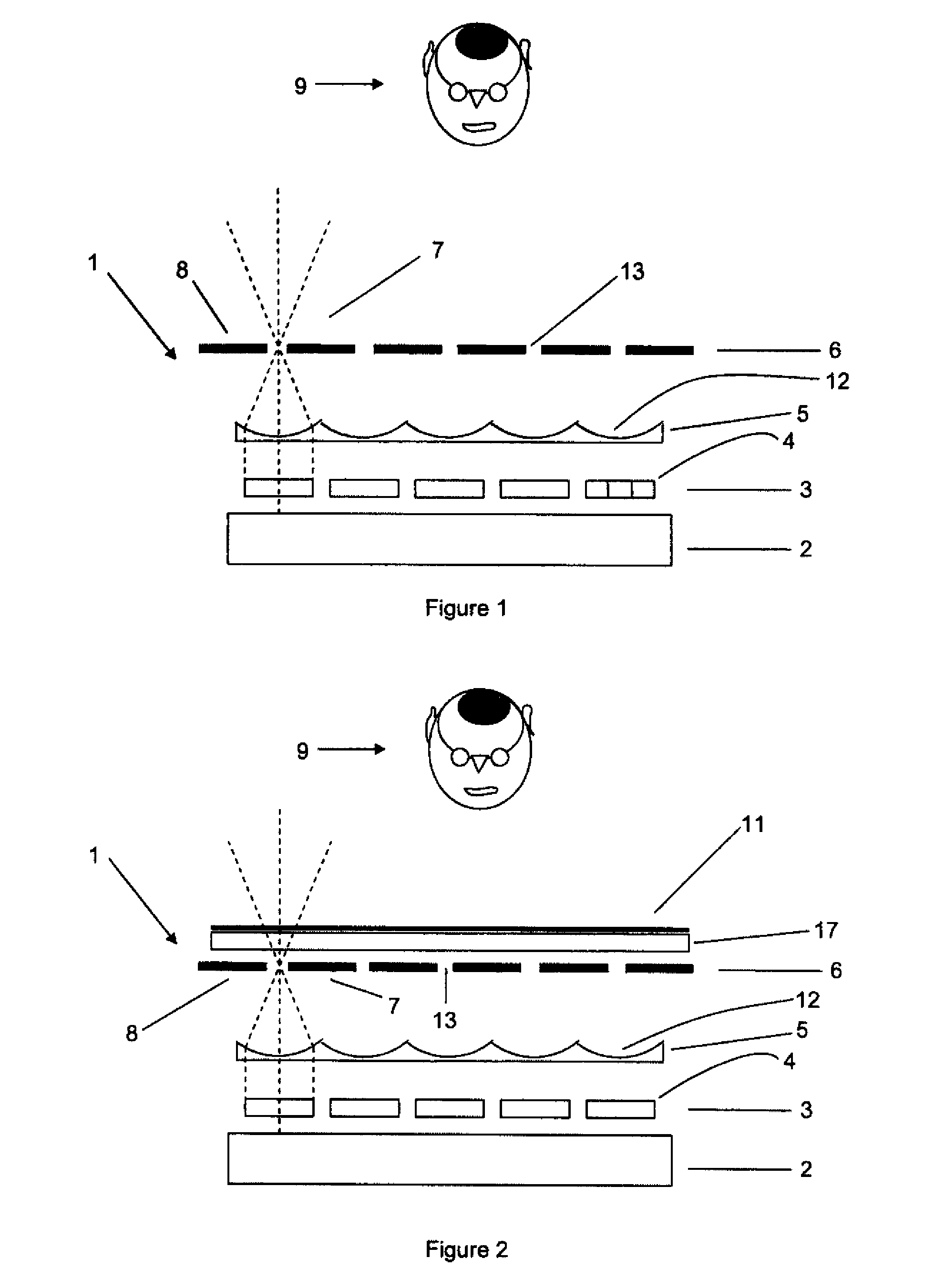
[0036]FIG. 1 schematically shows an embodiment of the disclosed device. FIG. 1 represents a cross section through a display screen according to the disclosure. The display screen 1 comprises an array 3 of image zones 4 (which may be pixels) backlit by a light source 2, typically flat, placed behind the array 3 of image zones 4. The flat light source 2 may be a diffusing plate. In a variant embodiment, the array 3 of pixels 4 is not backlit by a light source 2, but each pixel 4 itself constitutes a light source, for example by electroluminescence. As indicated above, each pixel 4 may be formed by a plurality of u...


PUM

PropertyMeasurementUnit
Flexibilityaaaaaaaaaa
Transparencyaaaaaaaaaa
Luminosityaaaaaaaaaa

Abstract

A display device, in particular digital display screen, with integrated photovoltaic cells, including (a) an array of image zones emitting light or backlit by a light source placed behind the array of image zones, (b) an array formed by a plurality of photovoltaic cells and a plurality of orifices, in which array two neighboring photovoltaic cells form an orifice, and (c) a lenticular array making it possible to focus the light emitted by the image zones into the orifice between two neighboring photovoltaic cells. The lenticular array of the display device is positioned between the array of image zones and the array of photovoltaic cells.

Description

CROSS REFERENCE TO RELATED APPLICATION[0001]Priority is claimed under 35 U.S.C. §119(e) to Provisional Application No. 61 / 533,828, filed Sep. 13, 2011.FIELD OF THE INVENTION[0002]The present disclosure relates to the field of display devices, and more particularly to the field of backlit display screens.BACKGROUND OF THE INVENTION[0003]Screens comprising a large number of backlit pixels have been known for some time and used in, for example, television sets, computers and portable devices of small size, such as, for example, mobile telephones, games consoles and calculators. The term “backlit” image zone connotes an image zone, which is situated in front of a light source which illuminates it from the rear. The image zone may for example be a pixel, a plurality of pixels or a part of a pixel (for example a liquid crystal pixel) or else a strip of film on which an image has been printed. In a backlit screen, a diffuse light source is placed behind the plane of the pixels, so as to im...

Claims


Application Information

Patent Timeline
IPC IPC(8): G09F13/04B29C65/48H05K13/04H01L31/048F21V5/04G02B30/00
CPCG02F1/133526G02F2001/13324G02F2001/133562Y02E10/52G09G2320/0693Y10T156/1089G02B3/0006H01L31/048H01L31/0468H01L31/0543Y10T29/49002G02F1/133305G02F1/13324G02F1/133562
Inventor GILBERT, JOELCARDI, PHILIPPETASSE, REMY
Owner GARMIN
Why Eureka
Try Eureka