Process for making a wall with a porous element for component cooling

a technology of porous elements and components, applied in the direction of laminated elements, machines/engines, light and heating apparatus, etc., can solve the problems of differential thermal expansion, difficulty in bonding different materials, and prior methods that did not provide different materials for the porous cooling elements and the structural elements of a componen

Active Publication Date: 2012-09-20
SIEMENS ENERGY INC
View PDF1 Cites 92 Cited by
  • Summary
  • Abstract
  • Description
  • Claims
  • Application Information

AI Technical Summary

Problems solved by technology

Prior methods did not provide different materials for the porous cooling elements and the structural elements of a component.
However, bonding different materials is challenged by differential thermal expansion when the bond is exposed to large temperature variations as in a gas turbine.

Method used


Image

  • Process for making a wall with a porous element for component cooling
  • Process for making a wall with a porous element for component cooling
  • Process for making a wall with a porous element for component cooling

Examples


Embodiment Construction

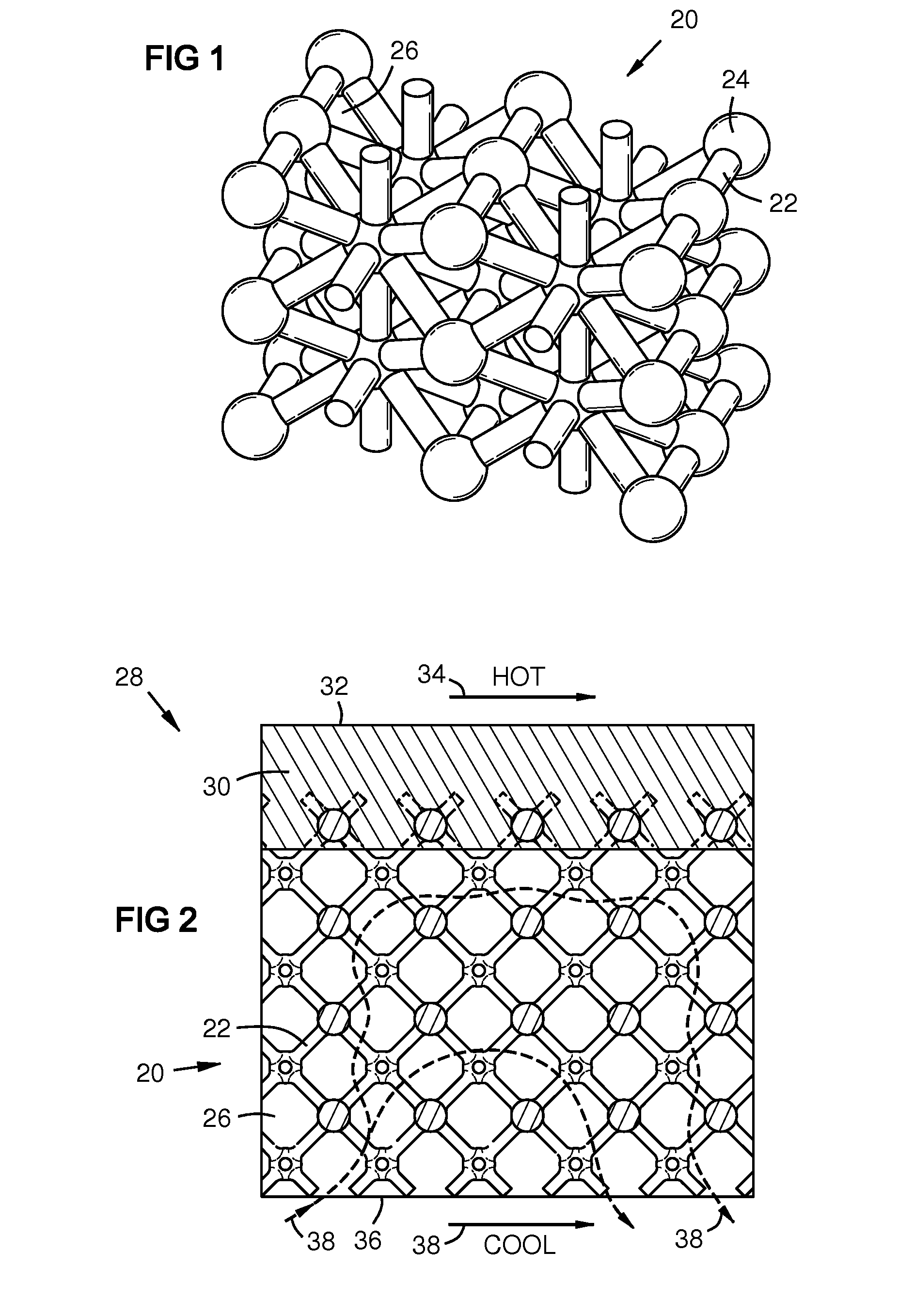
[0021]FIG. 1 shows a discrete porous construction 20 that may be used for cooling in the invention. The term “discrete” in this context means a construction with a geometry that is engineered and determinate, rather than random as with foam. Advantages of discrete porous constructions over random ones include strength, rigidity, and uniformity. A lattice geometry as in FIG. 1 is not a requirement of the invention, but is just one example of a discrete porous construction. It may comprise links 22 interconnected at nodes 24, providing passages 26 between the links. Such a construction may be formed by selective layer sintering or melting (SLS / SLM) or by other processes such as casting methods described in U.S. Pat. No. 7,141,812 of Mikro Systems Inc.

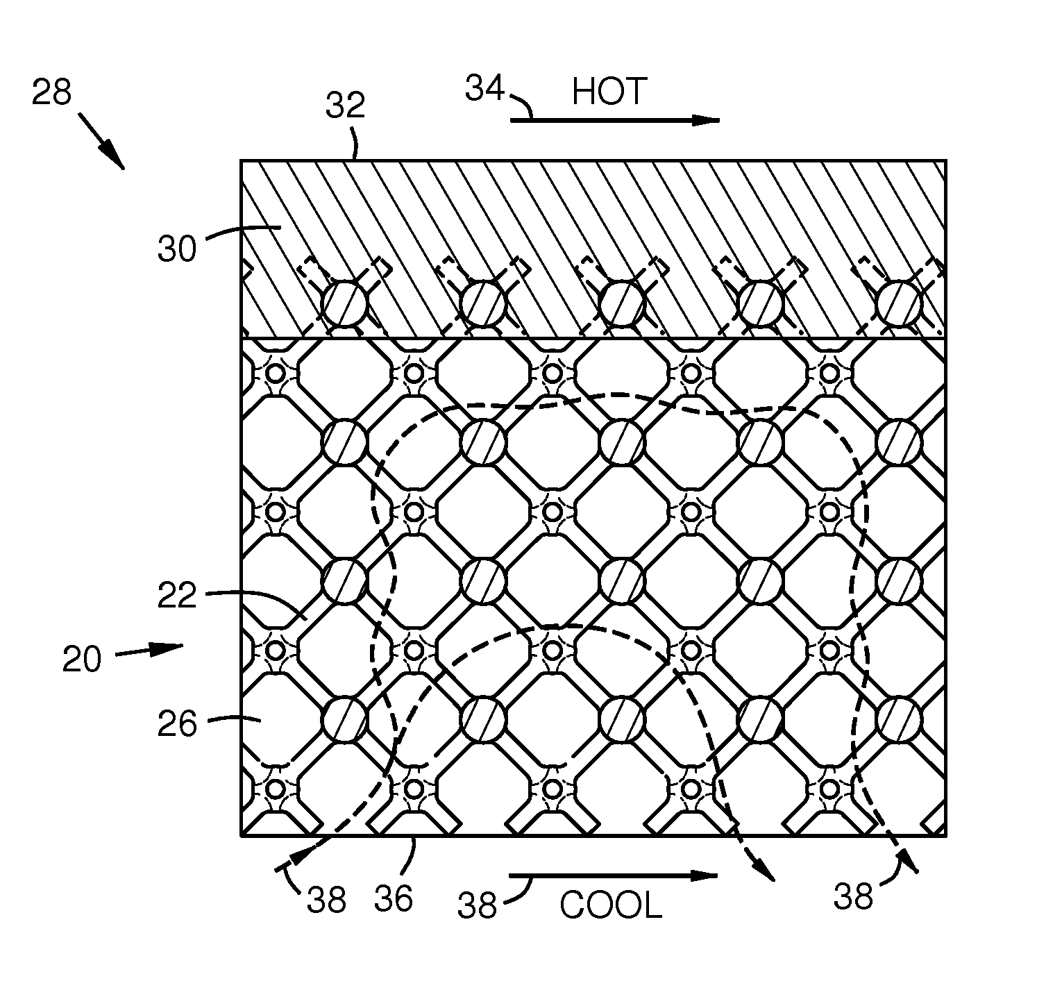
[0022]FIG. 2 shows a portion of a wall 28 formed by bi-casting a first structural layer 30 onto a porous construction 20. A first surface 32 of the wall 28 is exposed to a hot fluid 34, such as combustion gas. An opposed surface 36 of the...


PUM

PropertyMeasurementUnit
structural propertiesaaaaaaaaaa
thermal conductivityaaaaaaaaaa
temperatureaaaaaaaaaa

Abstract

A structural layer (30) may be bi-cast onto ligaments (62) extending from a porous cooling construction (20). The material of the structural layer may be optimized for high-temperature strength, while the material of the porous construction may be optimized for high thermal conductivity. A fugitive material (56) such as wax may be formed on the ligaments of the porous construction. A second fugitive material (58) such as ceramic may fill the remaining part of the porous construction. An investment casting shell (60) may be disposed around the porous construction and the fugitive materials. The first fugitive material may then be replaced with the material of the structural layer (30), and the second fugitive material may be removed to provide coolant paths (26). A second structural layer (52) may be bi-cast onto further ligaments (62) on a second side of the porous construction.

Description

FIELD OF THE INVENTION[0001]This invention relates to walls with porous elements for component cooling, particularly in turbine engines.BACKGROUND OF THE INVENTION[0002]Cooling of components such as gas turbine blades has been done by routing cooling air through channels in the component; passing the coolant through pores in the outer walls for film cooling; passing the coolant along interior surfaces of the walls for near-wall cooling; and / or directing jets of the cooling air against the walls for impingement cooling.[0003]In addition, porous constructions have been formed on component walls to thermally couple the coolant to the wall. Methods of manufacturing porous constructions for this purpose have included casting, selective metal sintering or melting (SLS, SLM), and others. The porous element may be formed separately and then bonded to the structural wall, or a porous element may be formed integrally with a wall in a single process. Examples of prior methods are found in U.S....

Claims


Application Information

Patent Timeline
Patent Type & Authority Applications(United States)
IPC IPC(8): B32B5/18B32B3/10B32B15/01B22D19/00
CPCB22D19/00B22D19/04B32B15/01F01D25/005F01D25/12Y10T428/12361Y10T428/12479Y10T29/49616Y10T29/49988Y10T29/4932F28F3/12F23R2900/00018
Inventor MORRISON, JAY A.SNIDER, RAYMOND G.JAMES, ALLISTER W.
Owner SIEMENS ENERGY INC
Why Eureka
Try Eureka