Compression system

a compression device and compression tube technology, applied in the field of compression devices, can solve the problems of difficult to correctly locate the puncture site in relation to the entrance site, and achieve the effect of stopping blood flow and facilitating correct positioning of the compression devi

Inactive Publication Date: 2012-09-20
ST JUDE MEDICAL COORDINATION CENT
View PDF3 Cites 24 Cited by
  • Summary
  • Abstract
  • Description
  • Claims
  • Application Information

AI Technical Summary

Benefits of technology

[0007]The object of the invention is thus to facilitate a correct positioning of a compression device to stop a blood flow from a puncture site.

Problems solved by technology

It may therefore be difficult to correctly locate the puncture site in relation to the entrance site.

Method used


Image

  • Compression system
  • Compression system
  • Compression system

Examples


Embodiment Construction

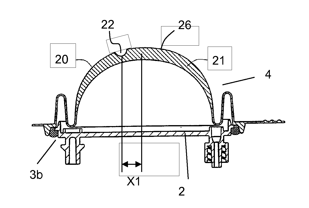
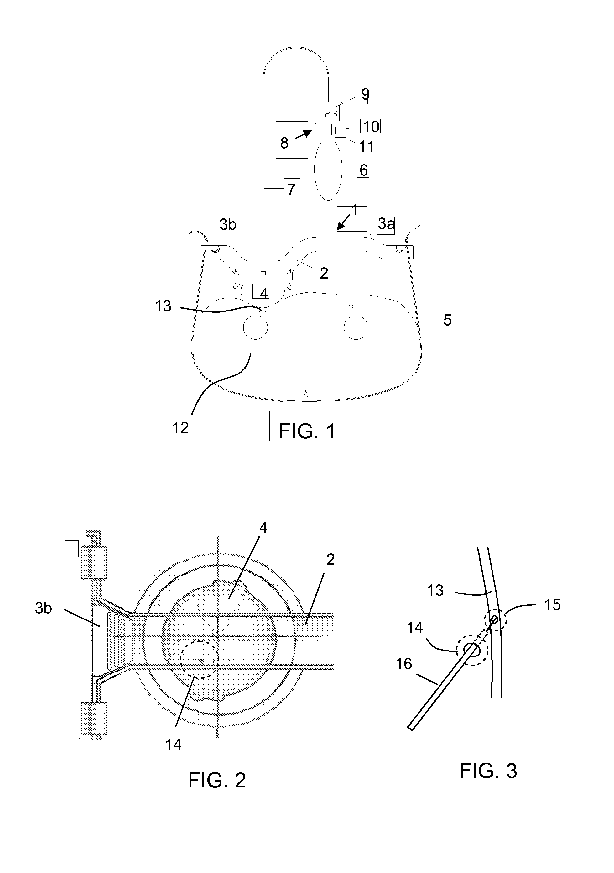
[0026]FIG. 1 illustrates a femoral compression device 1 as described in WO 2009 / 000665, and the present invention may be applied in connection with such device. The device 1 comprises a base plate 2 with two extensions 3a and 3b, a compression element 4, here in the shape of an inflatable and semi-spherical air cushion, a belt 5, a pump 6, an air connection 7, and an electric pressure gauge or manometer 8 with display 9. In use, compression element 4 is positioned over the femoral artery 13 of a patient 12, and the belt 5, which extends from the end of the first extension 3a, around the patient's body 12 and to the end of the second extension 3b, is tightened and secured by belt fasteners at the end of each extension. To apply pressure to the femoral artery 13, the inflatable semi-spherical air cushion 4 is inflated by the pump 6 to a certain pressure, which is measured by the manometer 8 and displayed on the display 9. The manometer 8 comprises further a vent knob 10, which is cove...


PUM


Abstract

The invention relates to a compression system (1) for compression against a puncture site of a vessel in a patient, comprising: a compression element (4) adapted to apply a pressure against said puncture site; a tightening unit (5) adapted to extend around a part of or the whole of the patient's body to fixate and to tighten the compression element against said puncture site; wherein the compression element is provided with a placement mark (18, 19, 22, 23, 24, 25) indicating where the compression element should be placed in relation to an entrance site through the skin of the patient made to reach said puncture site, in order to apply pressure against said puncture site.

Description

FIELD OF THE INVENTION[0001]The present invention relates to a compression system for compression of a vessel, and in particular to a compression system which facilitates correct placement of the system.BACKGROUND OF THE INVENTION[0002]To access a patient's vascular system for an invasive medical procedure such as catheterization or similar procedures, a puncture is made in e.g. the femoral artery or the radial artery. Following the medical procedure the flow of blood through the puncture site has to be stopped, so that haemostasis may begin as soon as possible. This may be done by using a compression device.[0003]One example of such a compression device is known from WO 2009 / 000665, describing a femoral compressing device for compressive bearing against the femoral artery of a patient. The device comprises a base plate, an inflatable air cushion, and a manometer connected to the inflatable air cushion. The device is fixed around the patient's body with a belt. In use, the inflatabl...

Claims


Application Information

Patent Timeline
Patent Type & Authority Applications(United States)
IPC IPC(8): A61F13/00
CPCA61B17/1325A61B17/135A61F5/30A61B2019/4836A61B2019/5437A61B2017/00907A61B2090/0807A61B2090/3937
Inventor DURING, ERIK
Owner ST JUDE MEDICAL COORDINATION CENT
Why Eureka
Try Eureka