
Motorcycle tire/wheel changing tool

a technology for changing tools and motorcycles, which is applied in the direction of wheel mounting devices, machine supports, cycles, etc., can solve the problems of wheel damage, multiple attempts, and ultimate failure to install

Active Publication Date: 2012-09-27
COMBS SAM
View PDF3 Cites 8 Cited by
  • Summary
  • Abstract
  • Description
  • Claims
  • Application Information

AI Technical Summary

Benefits of technology

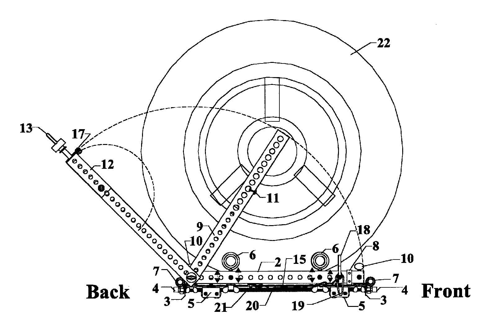
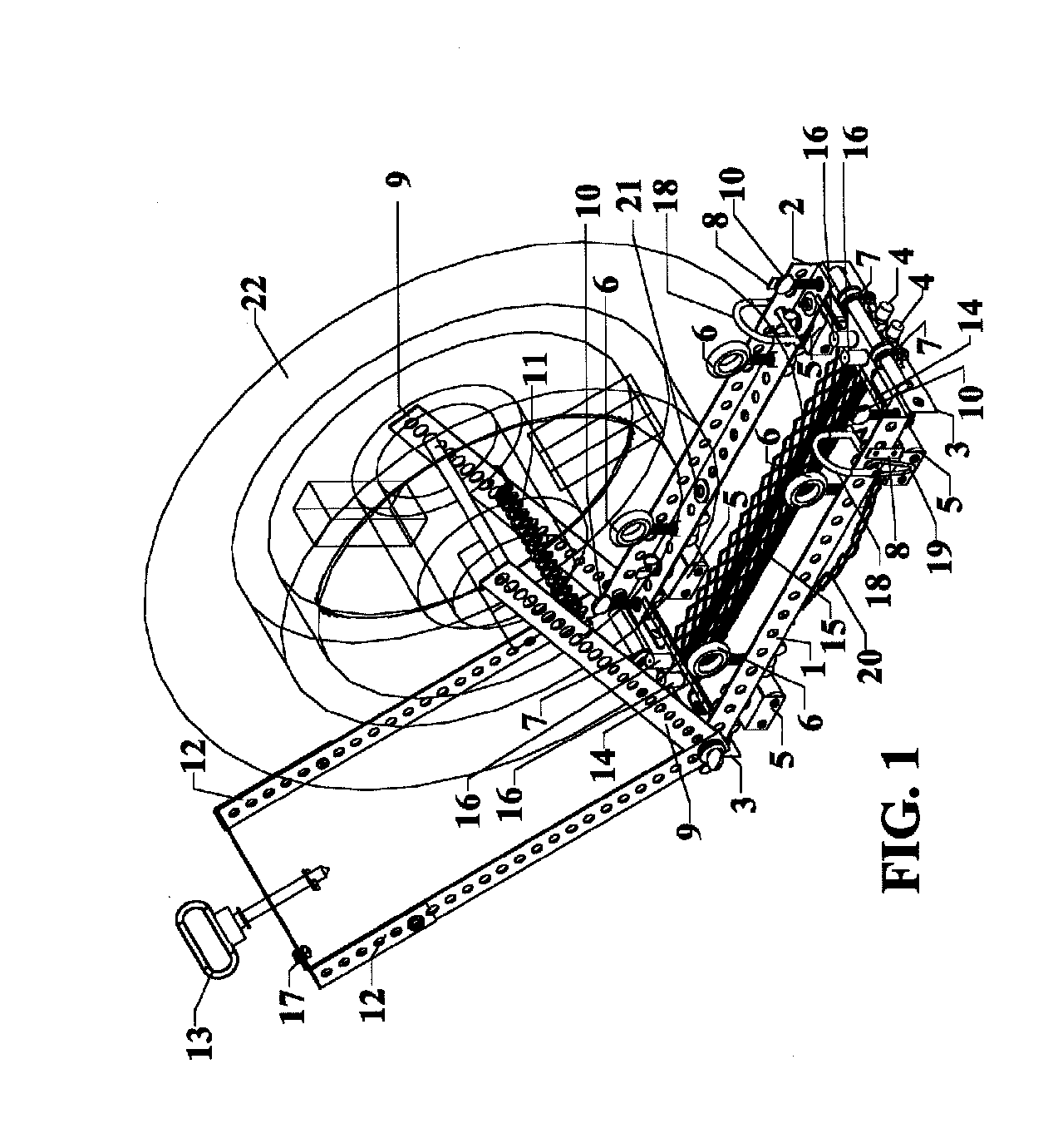
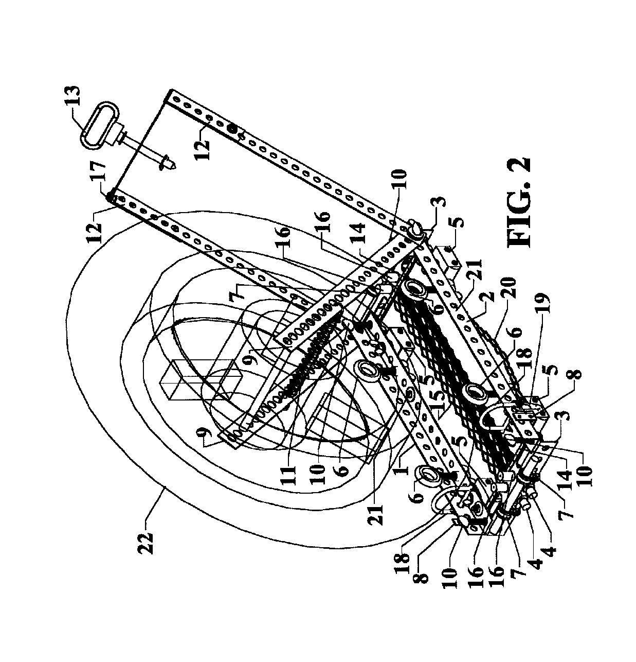
[0002]The Motorcycle Tire / Wheel Changing Tool includes a motorcycle wheel changing tool that engages and immobilizes the front or back wheel along with a front speedometer cable gear unit assembly, disc brake(s) (hereafter simply “wheel”), and spacers or back wheel spacers / disk brake / sprocket (hereafter simply “wheel”) in place on a rolling carriage that can be rolled around a garage, shop, or racing paddock and then be placed at the front or back wheel (in conjunction with any front of back wheel motorcycle lifting stand that is either double or single sided) to allow easy installation of the entire tire / wheel / spacer assembly (hereafter simply “wheel”) with a knockout rod (in place of the actual wheel axle).
[0003]It is the object of this disclosure to provide an easy means of holding a motorcycle wheel in place and immobile whether it be the front or back wheel in the process of changing the wheel.
[0004]It is a further object of this disclosure to provide ease of use for either the home or professional mechanic in the adjustment of this tool so that a motorcycle wheel can be installed in a timely manner and by one individual.

Problems solved by technology

Then one mechanic attempts to install the axle through the front forks or back swing arm while holding the spacers in place, while the second mechanic holds the wheel in place with his foot and / or hands which usually results in the failure to align the axle correctly, thereby causing multiple attempts and sometimes ultimate failure to install and / or damage to the wheel.

Method used


Image

  • Motorcycle tire/wheel changing tool
  • Motorcycle tire/wheel changing tool
  • Motorcycle tire/wheel changing tool

Examples


Embodiment Construction

[0024]Certain terminology is used herein for convenience only and is not to be taken as a limitation on the embodiments of a Motorcycle Tire / Wheel Changing Tool. In the drawings, the same reference letters are employed for designating the same elements throughout the several figures.

[0025]The words “right”, “left”, “front”, and “back” designate directions in the drawings to which reference is made. The words “inwardly” and “outwardly” refer to directions toward and away from, respectively, the geometric center of the motorcycle tire / wheel changing tool and designated parts thereof. The terminology includes the words above specifically mentioned, derivatives thereof, and words of similar import.

[0026]Like reference numerals designate like or corresponding parts throughout the various views and with particular reference to each of FIGS. 1-11 as delineated below.

[0027]FIGS. 1-3 show one embodiment of a Motorcycle Tire / Wheel Changing Tool and delineate perspective views from several ang...


PUM


Abstract

A motorcycle wheel changing tool is presented that utilizes a rolling carriage that immobilizes the front or back wheel utilizing flat steel swing arms and a tension spring that holds the wheel in place with a knockout retaining rod through the wheel. The entire unit can be rolled and / or lifted in place to work in conjunction with a motorcycle stand. There is a folding handle that expands or contracts to accommodate different size tire / wheel widths and can pull the unit. The rolling wheels can be raised or lowered for different motorcycles depending on the height of the bike in relation to the wheel stand. Additionally, four large eye hooks can be raised or lowered to secure the wheel. Two threaded rods are utilized that secure both angle ends in place to secure the unit so that it is perpendicular to the wheel and keeps the unit from flexing.

Description

BACKGROUND[0001]The concept of a tool holding either a front or back motorcycle wheel immobile while either installing or removing (hereafter simply changing) it is a new concept and doesn't appear to have been attempted in any of the prior art review that has been accomplished. In the observance of the act of changing wheels during a motorcycle race, the mechanic and / or two mechanics race out of the garage or pit area with a wheel and the related spacers to the motorcycle that has been raised either on a rear wheel bike stand or front wheel bike stand or both. Then one mechanic attempts to install the axle through the front forks or back swing arm while holding the spacers in place, while the second mechanic holds the wheel in place with his foot and / or hands which usually results in the failure to align the axle correctly, thereby causing multiple attempts and sometimes ultimate failure to install and / or damage to the wheel. In the home mechanics garage or the professional mechani...

Claims


Application Information

Patent Timeline
Patent Type & Authority Applications(United States)
IPC IPC(8): F16M13/00
CPCB60C2200/10B60B29/001
Inventor COMBS, SAM
Owner COMBS SAM
Learn More