Oil collecting device

Inactive Publication Date: 2012-09-27
MANVERS ENG
View PDF9 Cites 7 Cited by
  • Summary
  • Abstract
  • Description
  • Claims
  • Application Information

AI Technical Summary

Benefits of technology

[0087]The oil permeable base layer is flexible such that it can be rolled up for storage. The mat according

Problems solved by technology

Leakage or accidental spillage of fluids such as oil from machinery, in particular portable or automotive machinery used in civil engineering projects, can lead to pollution of the ground.
For example, engine oil, diesel fuel oil and hydraulic fluids can cause environmental damage.
There are stringent requirements for dealing with ground contamination which can be very costly for a contractor.
A problem with this type

Method used


Image

  • Oil collecting device
  • Oil collecting device

Examples


Embodiment Construction

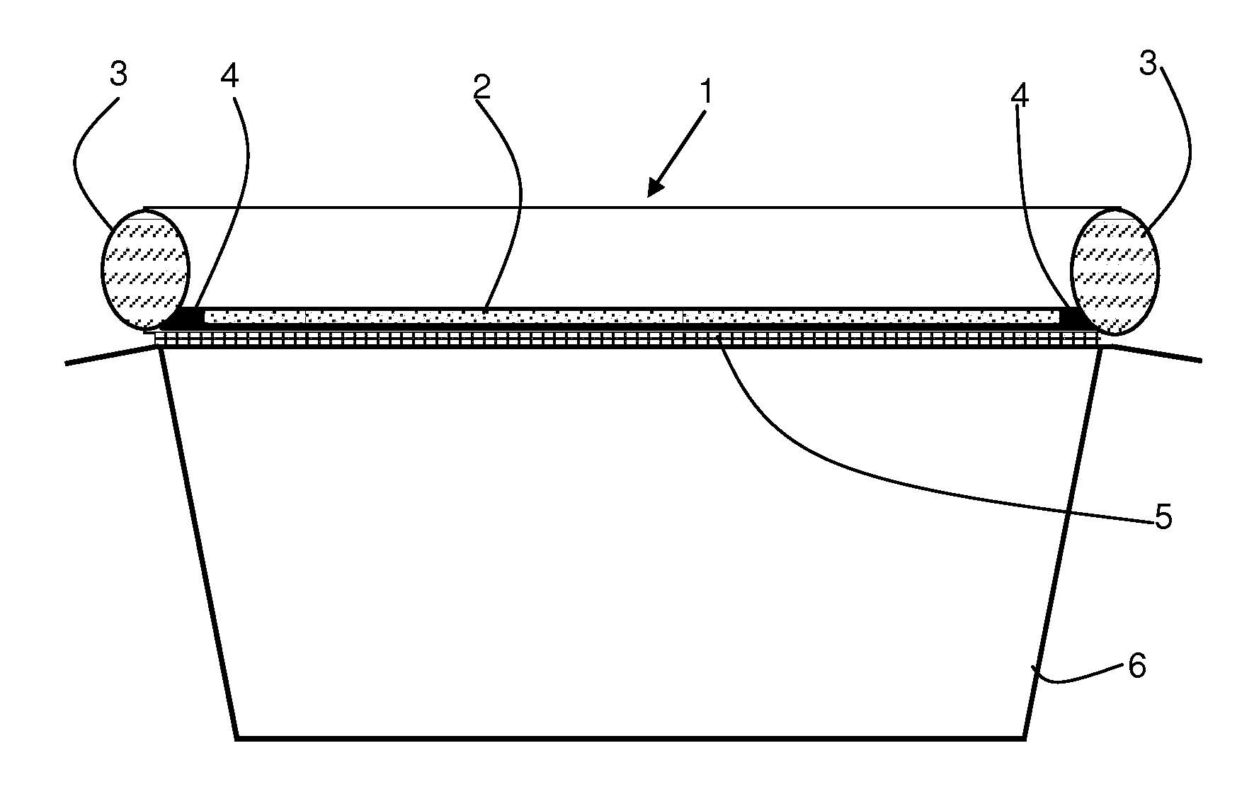
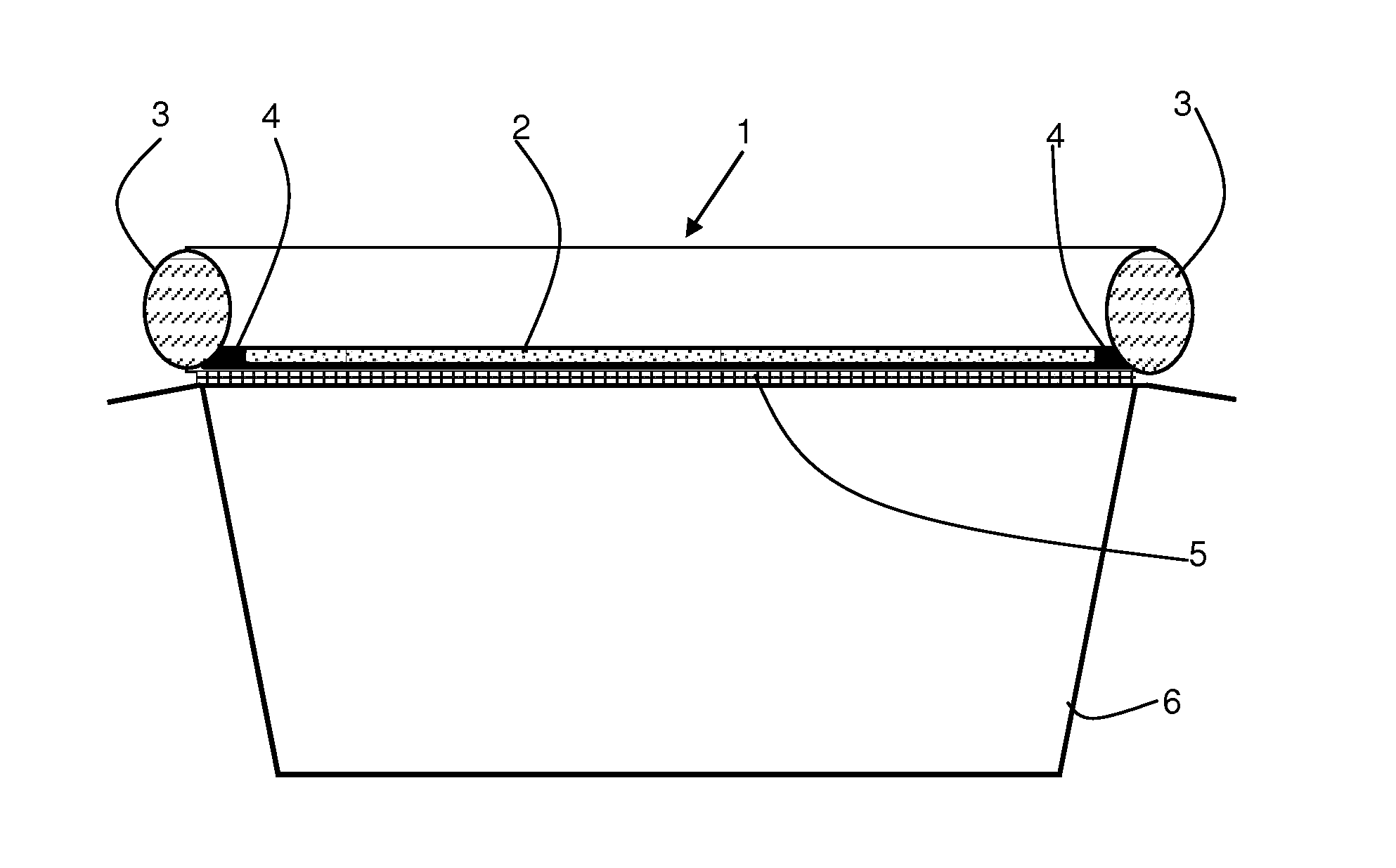
[0090]The collector shown in the drawing comprises a mat 1 having a base layer 2 and a wall 3 upstanding around the perimeter thereof. The mat can be rectangular. However it will be understood that the shape of the mat is not important. The shape can be varied, dependent upon the machinery beneath which it is to be used. The wall 3 is formed as a tubular fabric structure filled with polypropylene fibre material to give it sufficient rigidity to be self supporting in use. The height of the wall 3 above the base layer 2 is typically 50 mm to 100 mm.

[0091]The wall 3 may be continuous or it may be constructed in sections joined together at the corners. The wall 3 is provided with a flattened base for attachment to the base layer 2 around the periphery thereof.

[0092]The base layer 2 of the mat 1 is oil permeable. It is formed of an oil permeable hydrophobic felt layer. This layer is covered by a fabric material.

[0093]Several tests were conducted with different materials forming the hydro...


PUM

PropertyMeasurementUnit
Areaaaaaaaaaaa
Permeabilityaaaaaaaaaa
Oleophilicityaaaaaaaaaa

Abstract

A mat for use in a portable collector for machine fluids, the mat having a self supporting perimeter wall upstanding from a base layer, the base layer comprising a layer of an oil permeable hydrophobic material and the wall comprising a layer of water permeable oleophilic material, whereby oily fluid falling on the mat passes through the base layer and water falling on the mat escapes through the wall.

Description

FIELD OF THE INVENTION[0001]This invention relates to a collecting device for collecting oil for use in protecting the ground beneath machinery, for example portable plant used in civil engineering and the like.BACKGROUND TO THE INVENTION[0002]Leakage or accidental spillage of fluids such as oil from machinery, in particular portable or automotive machinery used in civil engineering projects, can lead to pollution of the ground. For example, engine oil, diesel fuel oil and hydraulic fluids can cause environmental damage. There are stringent requirements for dealing with ground contamination which can be very costly for a contractor. It has therefore become normal practice to use some form of collector beneath the machinery to collect and retain any fluids escaping from the machinery or spilled near it.[0003]One such oil collector is described in GB2428032. This portable collector comprises a mat having a self supporting perimeter wall upstanding from an impermeable base layer. The m...

Claims


Application Information

Patent Timeline
IPC IPC(8): B65D1/34B32B27/02B32B3/02D04H1/42D04H1/4291D04H1/46
CPCD04H1/42D04H1/4291Y10T428/237F16N31/006Y10T428/24777D04H1/46D04H1/4374C09K3/32F16N31/02
Inventor IBBOTSON, COLIN
Owner MANVERS ENG
Why Eureka
Try Eureka