Head-Mounted Display Device

a display device and head-mounted technology, applied in static indicating devices, instruments, optics, etc., can solve the problem of not ensuring a large interpupillary distance adjustment width, and achieve the effect of enhancing the effect of pupil position adjustmen

Inactive Publication Date: 2012-09-27
OLYMPUS CORP
View PDF6 Cites 77 Cited by
  • Summary
  • Abstract
  • Description
  • Claims
  • Application Information

AI Technical Summary

Benefits of technology

[0006]When the light is reflected for odd number of times within the light guide prism as described in JP 2010-226661 A, there may be obtained a larger effect on pupil position adjustment due to the relative movement of the light guide prism and the video display element, as compared to the case where the light is reflected for even number of times. FIGS. 7A and 7B illustrate how the optical path changes in a head-mounted display device, which includes: a video display element 101; and a light guide prism 102 having an eyepiece lens 103 fixed to an emitting portion for emitting video light, when the video display element 101 and the light guide prism 102 are relatively displaced so as to adjust the pupil position. In FIG. 7A, video light is reflected for even number of times (twice) within the light guide prism 102, while in FIG. 7B, video light is reflected for odd number of times (five times). In the drawings, the solid lines and the dashed lines each render the configuration and the optical axis path before and after the movement, respectively, and the light guide prism 102 is moved substantially parallel to the video display element 101 which remains fixed. It is apparent from FIGS. 7A and 7B that an interpupillary distance adjustment width L2 is small relative to the movement width L1 of the light guide prism 102 when light is reflected twice within the light guide prism 102, whereas an interpupillary distance adjustment width L3 is larger relative to the movement width L1 of the light guide prism 102 when light is reflected five times within the light guide prism 102. In other words, when light is reflected for odd number of times within the light guide prism, a slight mechanical adjustment has great effect on interpupillary distance adjustment.

Problems solved by technology

However, in the head-mounted display device configured as described above, due to the air gap thus formed, an external casing and / or a complicated holding mechanism become necessary in order to hold the eyepiece lens with respect to the light guide prism.
However, such a configuration cannot ensure a large interpupillary distance adjustment width.

Method used


Image

  • Head-Mounted Display Device
  • Head-Mounted Display Device
  • Head-Mounted Display Device

Examples


first embodiment

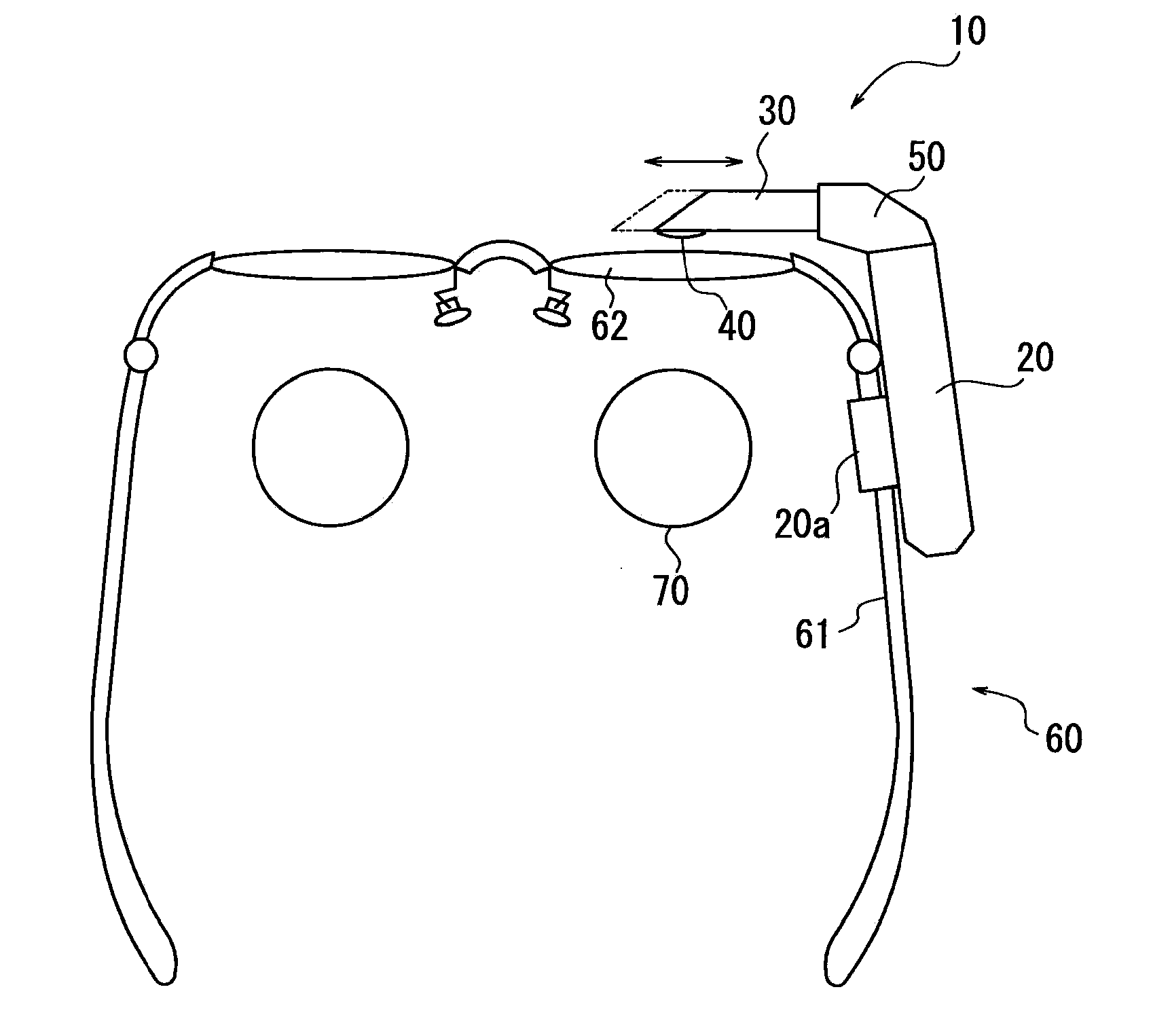
[0034]FIG. 1 is a plan view schematically illustrating a head-mounted display device 10 according to a first embodiment of the present invention, which is mounted on spectacles 60. The head-mounted display device 10 includes an eyepiece optical portion which is mainly formed of a main body portion 20, a light guide prism 30, and an eyepiece lens 40. When mounting the head-mounted display device 10 onto the spectacles 60, the main body portion 20 is attached, by means of a support portion 20a or the like, to a temple on the right side of a frame 61 of the spectacles 60 worn on the head of a wearer.

[0035]The main body portion 20 extends along the frame 61 of the spectacles 60 to the front of the wearer, and a leading end thereof is coupled to the light guide prism 30 via an attachment portion 50 to be described later, on the side of a right spectacle lens 62. The light guide prism 30 extends, in front of the right spectacle lens 62 of the spectacles 60, substantially horizontally from...

second embodiment

[0055]FIG. 5 is a diagram schematically illustrating a configuration of an optical system of a head-mounted display device according to a second embodiment of the present invention, which is a top view from the head side of the wearer. This embodiment is different from the first embodiment of FIG. 2 in that the light guide prism 30 is cut out in portion 37 where light beams do not pass through in any case where the light guide prism 30 and the video display element 21 are in either one of the relative positions. The second optical surface 32 of FIG. 2, which does not serve as a reflecting surface for video light, is cut out entirely. Further, the light guide prism 30 has surfaces 38a, 38b at a section left after the cutout, the surfaces being formed as light-absorbing surfaces, similarly to the second optical surface 32 of FIG. 1. Other configurations and operations are similar to those of the first embodiment, and thus the description thereof is omitted with the same constituent el...

third embodiment

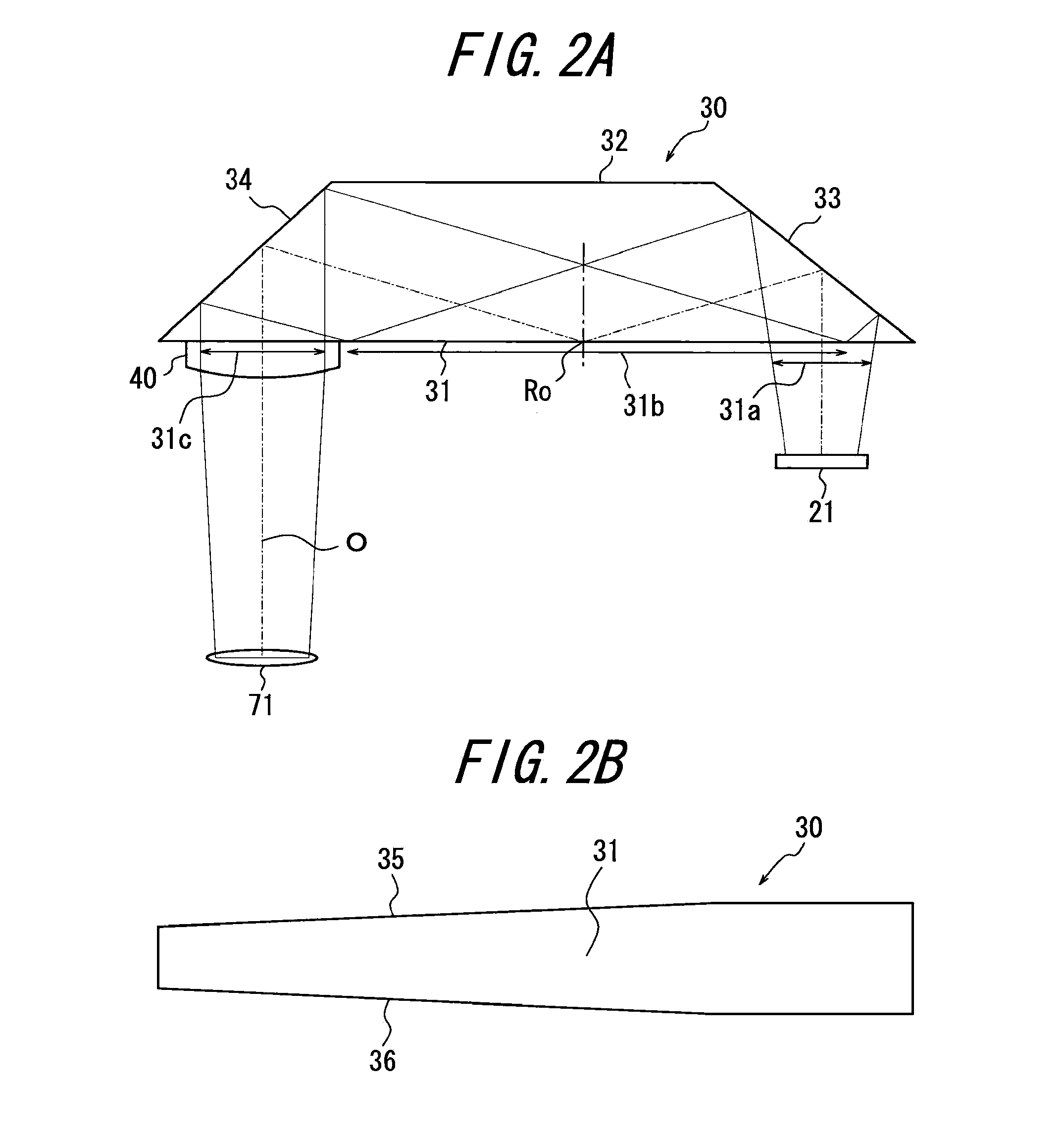
[0057]FIG. 6 is a diagram schematically illustrating a configuration of an optical system of a head-mounted display device according to a third embodiment of the present invention, which is a top view from the head side of the wearer. The first optical surface 31 of the light guide prism 30 of FIG. 6 is bent between the emitting portion 31c and a portion including the incident portion 31a and the reflecting portion 31b, so that a normal direction of an exiting surface, through which the video light exits from the emitting portion is directed toward a pupil of the wearer. The exiting surface of the emitting portion 31c on the first optical surface 31 is tilted so as to be aligned along the lower edge of light beams of video light reflected by the reflecting portion 31b. In other words, the light guide prism 30 is formed in a shape without a region where light fluxes exiting from the emitting portion 31c on the first optical surface 31 pass through while light reflected by the reflect...


PUM


Abstract

A head-mounted display device includes: a light guide prism in a polyhedron shape having a first optical surface facing a wearer side in a mounted state, and a third and a fourth optical surfaces each forming an acute interior angle with the first optical surface; a video display portion for emitting video light toward an incident portion on the first optical surface; and an eyepiece lens cemented to or integrally formed with an emitting portion on the first optical surface. Video light incident on the incident portion on the first optical surface is reflected by the third optical surface, the first optical surface and the fourth optical surface, and is emitted toward a pupil direction of the wearer on an optical axis of the eyepiece lens. The incident portion and the reflecting portion overlap each other in part while the emitting portion avoids overlapping with the reflecting portion.

Description

CROSS-REFERENCE TO RELATED APPLICATION[0001]The present application claims priority from Japanese Patent Application No. 2011-066168, filed on Mar. 24, 2011, the content of which is incorporated herein by reference.TECHNICAL FIELD[0002]The present invention relates to a head-mounted display device.RELATED ART[0003]There has been known a head-mounted display device in which a light guide prism for guiding video light emitted from an video display element and an eyepiece lens for observing, as a virtual image, a video image from the video display element are used in combination, so that the video image can be observed as an aerial image displayed in front of a visual field.[0004]In particular, for a head-mounted display device which is also designed for outdoor use, it is important to reduce the device size. For example, there has been proposed a device in which a video display element and a light guide prism are separately held by different portions (such as a frame and a lens) of sp...

Claims


Application Information

Patent Timeline
Patent Type & Authority Applications(United States)
IPC IPC(8): G09G5/00
CPCG02B2027/0178G02B27/0172
Inventor SUGIHARA, RYOHEI
Owner OLYMPUS CORP
Why Eureka
Try Eureka