
Method and Apparatus for Controlling Laser Transmissions for Enhanced Safety

a laser transmission and enhanced safety technology, applied in the field of laser systems, can solve the problems of limiting personnel exposure, not always possible, and affecting the safety of laser sensing systems intrinsically non-eye-safe, and achieve the effect of enhancing the safety of intrinsically non-eye-safe limited-range laser sensing systems

Active Publication Date: 2012-09-27
PERATON INC
View PDF4 Cites 35 Cited by
  • Summary
  • Abstract
  • Description
  • Claims
  • Application Information

AI Technical Summary

Benefits of technology

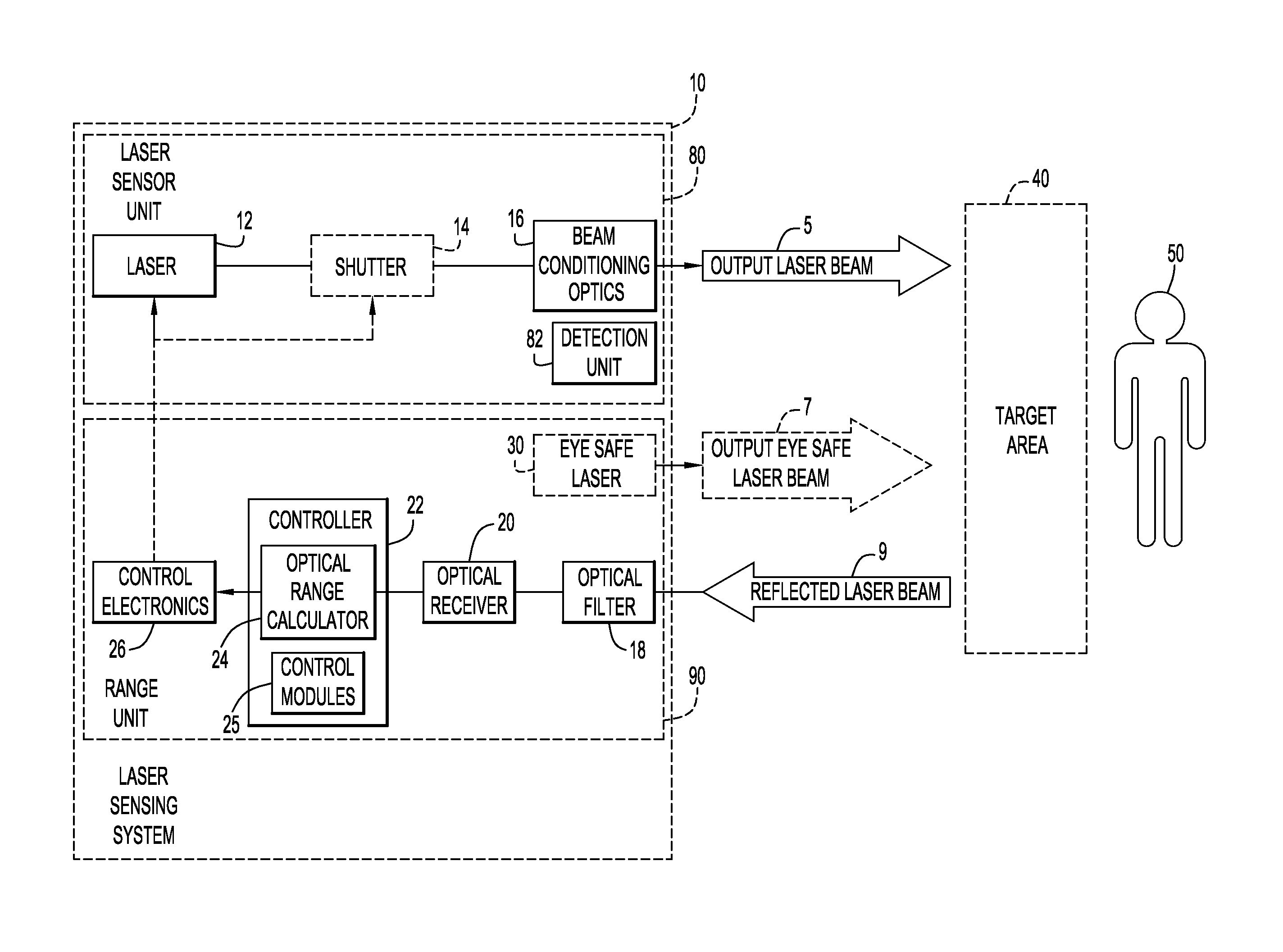
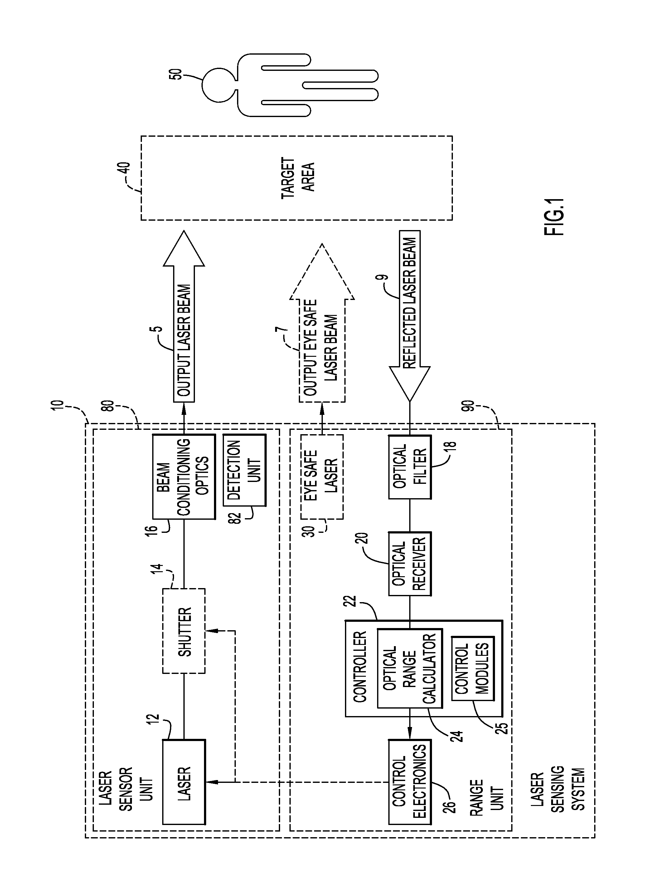
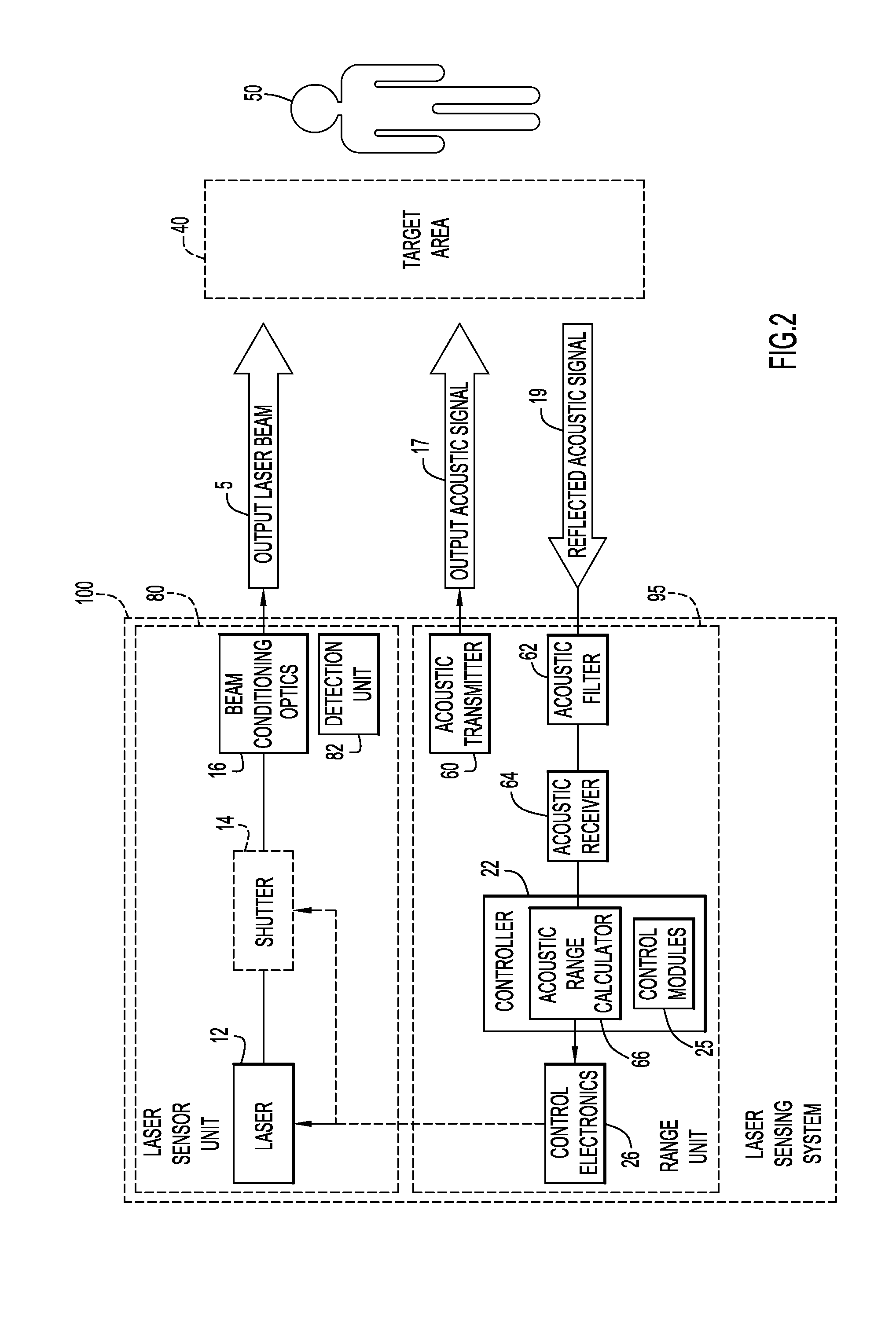
[0007]According to an embodiment of the present invention, the level of safety of an intrinsically non-eye-safe limited-range laser sensing system is enhanced for persons or other objects (e.g., animals, etc.) situated outside a spatial interval defining the limited operating range of the laser sensing system. The laser sensing system typically has an operating range limited to a well-defined spatial interval (e.g., an interval within 20 cm of a solid target under interrogation by the laser sensing system, the entire distance between the laser sensing system and a hard target that stops the interrogating laser beam, etc.). The laser sensing system interrogates a hard target (e.g., including solid substances and non-solid but optically opaque substances (e.g., a liquid, a gas, a cloud, etc.) that stops the non-eye-safe laser beam (e.g., or attenuates it sufficiently to render it eye-safe)). For example, the laser sensing system may interrogate a chemical droplet, biological material, or an explosive residue on a wall, table, vehicle exterior, or the ground. The laser sensing system may also sample an intervening region of air (e.g., interrogating gases emanating from a vehicle or a smokestack with a hard backstop to the laser beam, etc.).
[0009]The operating range may be determined from intrinsic hardware limitations (e.g. the laser sensing system is unable to efficiently detect outside a given spatial interval based upon its optical design) and / or an adaptive controller (e.g. when a target surface is detected within the operating range, the laser sensing system may automatically limit the operating range to a smaller spatial interval enclosing the target in order to enhance eye-safety by disabling transmission of the non-eye-safe laser when an object is detected outside that adaptive operating range). The controller may adaptively track the target distance to change the location (and possibly, width) of the adaptive spatial interval defining the operating range as the distance from the laser sensing system to the target surface under investigation varies. The controller may autonomously control the extent of the operating range (e.g., based upon three dimensional (3-D) mapping of the entire target, or the user may be allowed to enter information to better define the operating range for a given interrogation scenario).

Problems solved by technology

These sensors typically have a very short effective range.
However, this is not always possible due to limitations of technology, or the attributes of the underlying phenomenology that the sensor employs (e.g., Raman scattering is most efficient in the ultraviolet region).
Moreover, limiting personnel exposure, either by excluding all personnel or by requiring personnel to wear personal protective equipment (PPE), may not be possible.
In some cases, the exclusion zone may be too large to even render this approach feasible.
Present invention embodiments do not provide protection for persons within the operating range of the laser sensing system (since other devices such as passive infrared detectors may be used for that purpose), and do not protect against specular reflections or scattering of the non-eye-safe laser beam from a target within the operating range.
Such light may propagate outside the operating range and be hazardous.

Method used


Image

  • Method and Apparatus for Controlling Laser Transmissions for Enhanced Safety
  • Method and Apparatus for Controlling Laser Transmissions for Enhanced Safety
  • Method and Apparatus for Controlling Laser Transmissions for Enhanced Safety

Examples


Embodiment Construction

[0016]Present invention embodiments protect nearby persons or other objects (e.g., animals, etc.) that are outside an operating range of a laser sensing system by disabling transmission of a non-eye-safe laser beam. The beam transmission is disabled (e.g., including interruption or termination of the non-eye-safe laser beam, or modifying the non-eye-safe laser beam to be eye-safe) in response to no detection of a hard or intended target (e.g., including solid substances and non-solid but optically opaque substances (e.g., a liquid, a gas, a cloud, etc.) that stops the non-eye-safe laser beam (e.g., or attenuates it sufficiently to render it eye-safe)) within the operating range of the laser sensing system, or when an object is detected between the laser sensing system and the spatial interval that defines the operating range. For example, if the operating range of a laser sensing system is 0.5 to 3.5 meters, and the range to a reflecting or scattering surface impacted by a transmitt...


PUM


Abstract

According to a present invention embodiment, safety is enhanced for a non-eye-safe limited-range laser sensing system. The laser sensing system typically has an operating range limited to a well-defined spatial interval. A range measurement is utilized to control emissions of the non-eye-safe laser. In particular, when the range to a target is outside the designed spatial interval defining the operating range of the laser sensing system, transmission of the non-eye-safe laser beam is disabled or rendered non-hazardous. In other words, the transmission of the non-eye-safe laser beam is disabled in response to no detection of a hard target within the operating range of the laser sensing system, or when an object is detected between the laser sensing system and the spatial interval that defines the operating range. The target distance may be tracked to change the location (and possibly, width) of the adaptive spatial interval defining the operating range.

Description

BACKGROUND[0001]1. Technical Field[0002]Present invention embodiments pertain to laser systems. In particular, present invention embodiments pertain to controlling transmissions of non-eye-safe laser signals from a laser sensing system to provide enhanced safety for nearby objects (e.g., persons, animals, etc.) situated outside the boundaries of the operating range of the laser sensing system.[0003]2. Discussion of Related Art[0004]Active laser sensors transmit a laser pulse to interrogate a substance, and detect a response from the substance to the transmitted laser pulse. For example, Raman sensors detect return or scattered light with constituent colors based on vibrational modes excited in the chemical compound being interrogated. Other sensors may employ other phenomenologies such as Laser Induced Breakdown (LIB) or Photo-thermal Induced physical phenomena. In each of these applications, the surface of the object must be illuminated with sufficient laser energy to stimulate the...

Claims


Application Information

Patent Timeline
Patent Type & Authority Applications(United States)
IPC IPC(8): G01C3/08G01S15/08G01S17/04G01S17/87
CPCG01S17/87G01S17/026G01S17/04
Inventor LAVALLEY, HOWARD N.CHYBA, THOMAS H.
Owner PERATON INC
Learn More