Fluted osteotome and surgical method for use

a fluted osteotome and surgical method technology, applied in the field of osteotomes, can solve the problems of unintentional displacement or fracture of the labial plate of bone, limited treatment of mandibular sites, and many patients who do not tolerate the osteotome technique well, and achieves the effects of high controllability, improved controllability, and effective expansion and simultaneous compression of bone material

Active Publication Date: 2012-09-27
HUWAIS IP HLDG
View PDF10 Cites 48 Cited by
  • Summary
  • Abstract
  • Description
  • Claims
  • Application Information

AI Technical Summary

Benefits of technology

[0017]This invention overcomes the disadvantages and shortcomings of prior art osteotome techniques offering an atraumatic alternative to the traditional mallet-driven osteotomes without any disadvantages of rotary expander screw tap systems. The present surgical method and accompanying surgical tool for implementing the method provides a highly controllable, relatively fast and effective technique for expanding an initial osteotomy to receive a dental implant. By forcibly rubbing the burnishing edges of the osteotome against the interior surfaces of the osteotomy, th...

Problems solved by technology

Treatment of mandibular sites is often limited due to the increased density and reduced plasticity exhibited by the bone.
Additionally, since the osteotome is inserted by hammering, the explosive nature of the percussive force provides limited control over the expansion process, which often leads to unintentional displacement or fracture of the labial plate of bone.
Many patients do not tolerate the osteotome technique well, frequently complaining about the impact from the surgical mallet.
Thus, the rate of bone expansion is a direct and unalterable function of the rate at which the surgeon turns the expander tool, and the surgeon is unable to vary other parameters such as pressure and/or rotation rate to achieve an optimum expansion rate.
Thus, a typical osteotomy kit may include 4-6 expander screw taps which make the kit cost relatively expensive.
Another disadvantage is that each expander screw tap takes...

Method used


Image

  • Fluted osteotome and surgical method for use
  • Fluted osteotome and surgical method for use
  • Fluted osteotome and surgical method for use

Examples


Embodiment Construction

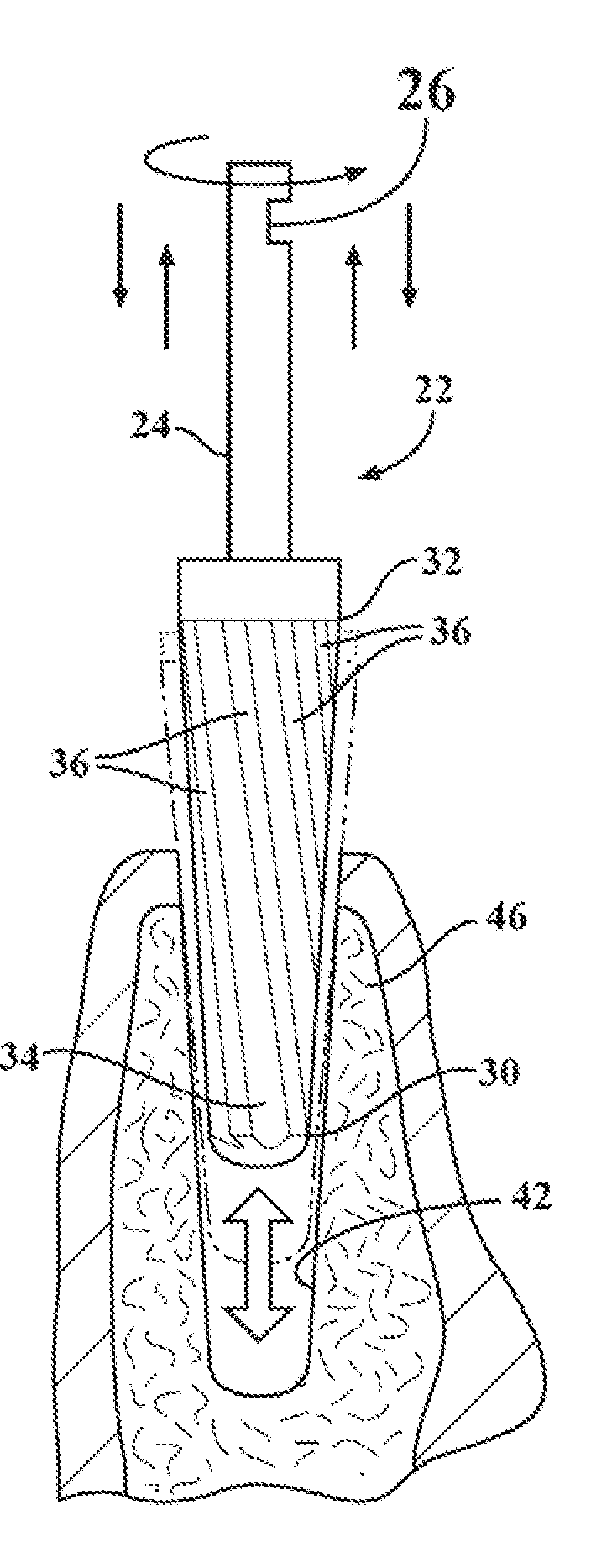
[0044]Referring to the figures wherein like numerals indicate like or corresponding parts throughout the several views, a burnishing osteotome according to the present invention is generally shown at 22 in FIGS. 4-11 and 13. The osteotome 22 comprises a longitudinally extending shank 24. The shank 24 has a coupling 26 at one end thereof to attach to a rotary input such as from a surgical motor having speed and torque controls. The osteotome 22 also includes a working end 28. The working end 28 extends longitudinally from the shank 24 opposite the coupling 26, and has a length of approximately 11-15 mm, although longer or shorter lengths may also be fashioned to suit the application. As perhaps best shown in FIG. 5, the working end 28 has a taper along at least a portion of its length. A leading distal tip 30 of the working end 28 defines a minimal outer diameter, and an upper end 32 defines a maximum outer diameter of the tapered portion. The difference between the minimal outer dia...


PUM


Abstract

A surgical method and tool for expanding an initial osteotomy (42) to receive a dental implant (44). An osteotome (22) having a tapered working end (28) is inserted into the initial osteotomy (42). The initial osteotomy (42) is enlarged by simultaneously rotating and pushing the working end (28) of the tapered osteotome (22) into the osteotomy (42). One or more burnishing edges (40) concentrate the pushing and rotational force in outward normal and tangential component forces against the interior surface of the osteotomy (42) to incrementally expand the osteotomy (42) with little to no removal of bone material (46). The inserting and enlarging steps are repeated, as needed, with progressively larger tapered osteotomes (22) until an osteotomy (42) of predetermined size is achieved. Finally, a fixture portion of a dental implant (44) is installed into the expanded osteotomy (42).

Description

CROSS REFERENCE TO RELATED APPLICATIONS[0001]This application claims priority to Provisional Patent Application No. 61 / 466,579 filed Mar. 23, 2011, the entire disclosure of which is hereby incorporated by reference and relied upon.BACKGROUND OF THE INVENTION[0002]1.Field of the Invention[0003]The invention relates generally to osteotomes, and more particularly to surgical methods for expanding an initial osteotomy to receive a dental implant.[0004]2. Related Art[0005]In its most basic form the placement of a dental implant requires a preparation into the bone using either hand osteotomes or precision drills with highly regulated speed to prevent burning or pressure necrosis of the bone. After a variable amount of time to allow the bone to grow on to the surface of the fixture portion of an implant, a restoration can be placed on the fixture. See for example FIG. 1.[0006]According to current techniques, at edentulous (without teeth) jaw sites that need expansion, a pilot hole is bore...

Claims


Application Information

Patent Timeline
IPC IPC(8): A61C8/00A61C3/02
CPCA61C8/0089A61B17/1604A61B17/885A61B17/1615A61C3/02
Inventor HUWAIS, SALAH
Owner HUWAIS IP HLDG
Why Eureka
Try Eureka