Electronic device control system, electronic device and electronic device control method

Inactive Publication Date: 2012-09-27
SHARP KK
View PDF8 Cites 11 Cited by
  • Summary
  • Abstract
  • Description
  • Claims
  • Application Information

AI Technical Summary

Benefits of technology

[0006]An object of the present invention is to provide an electronic device control system in which a client terminal and an electronic device capable of outputting an image are connected to a network, which is capable of restricting a function on the electric device side cor

Problems solved by technology

However, in the system described in Japanese Laid-Open Patent Publication No. 2006-172094, an administrator sets a function to be restricted, and a user is thus not able to confirm whether or not to be able to perform desired output due to function restriction until outputting.
Additionally, even with the technique described in Japanese

Method used


Image

  • Electronic device control system, electronic device and electronic device control method
  • Electronic device control system, electronic device and electronic device control method
  • Electronic device control system, electronic device and electronic device control method

Examples


Embodiment Construction

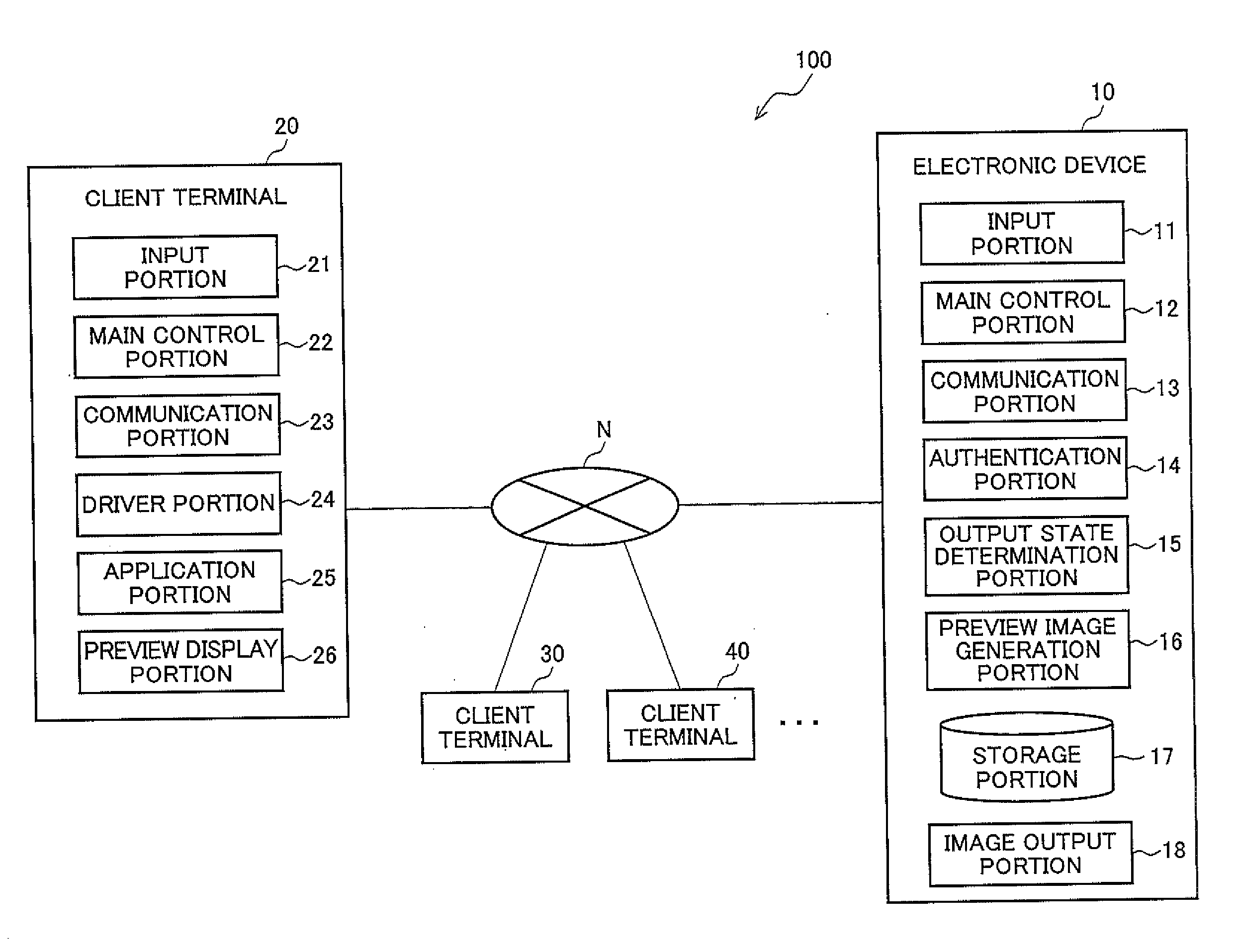
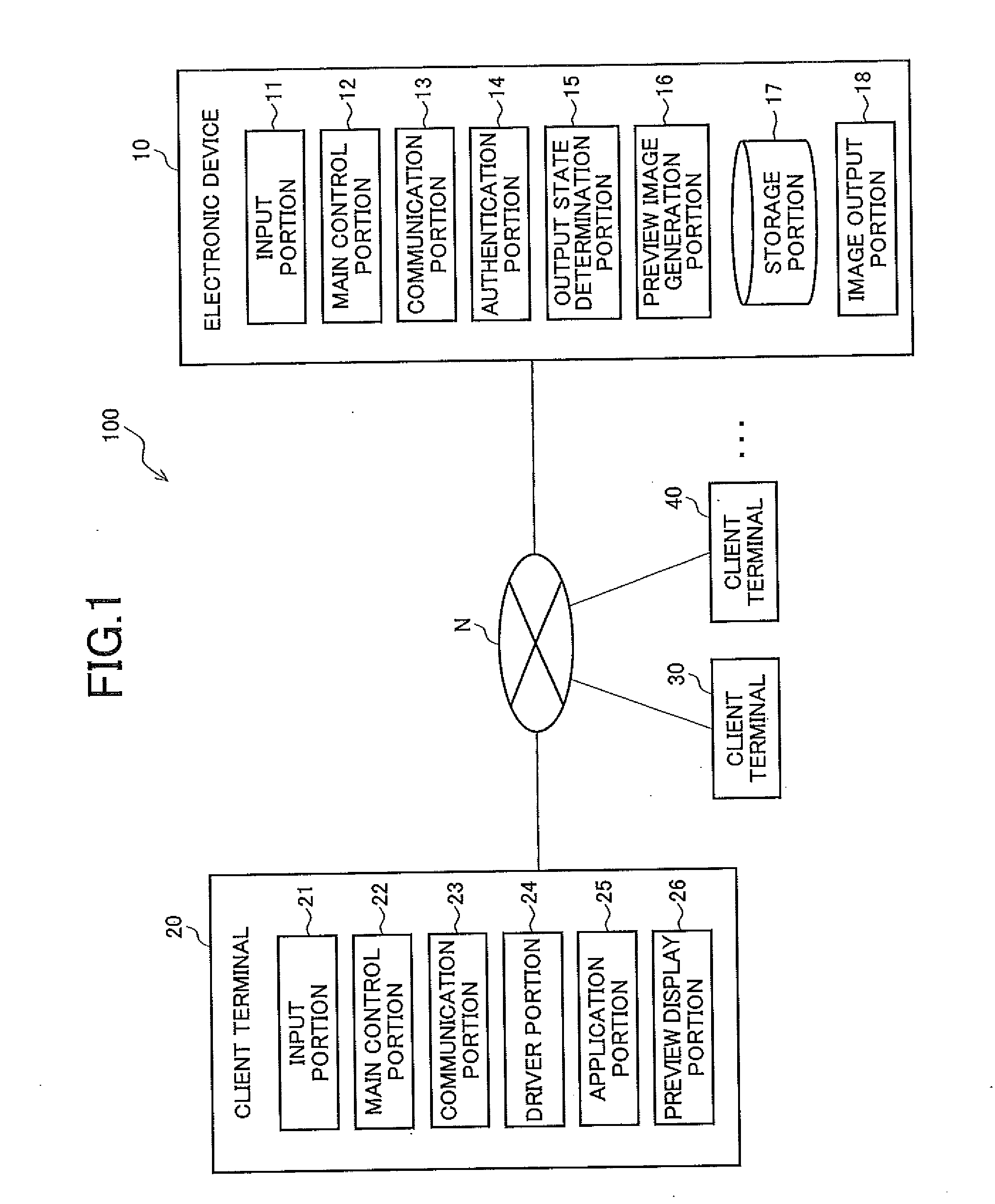
[0024]FIG. 1 is a block diagram showing a schematic configuration of an electronic device control system according to an embodiment of the present invention. In an electronic device control system 100 according to the present embodiment illustrated in FIG. 1, an electronic device 10 is connected to a client terminal 20 via a network N so as to be able to communicate mutual data.

[0025]Note that, description will be given for a system configuration in which only one unit for each of the client terminal 20 and the electronic device 10 is connected, however, the system configuration is not limited thereto, and as illustrated in an example in which client terminals 30 and 40 are connected to the network N, a system in which a plurality of the client terminals 20 are connected to the network N is also applicable likewise. Of course, it is similarly applicable also to a system in which a plurality of the electronic devices 10 are connected to the network N, and the same is true also in a s...


PUM


Abstract

An electronic device includes an authentication portion for performing user authentication according to an authentication request including the user information that is sent together with image data from a client terminal; an output state determination portion for determining an output state of an image for the image data depending on the user information in a case where the user authentication is successfully performed; a preview image generation portion for generating a preview image corresponding to the output state; and a sending portion for sending to the terminal a result of the user authentication to which the preview image is added only in a case where the user authentication is successfully performed. A preview display portion displays an execution button for instructing the electronic device to execute image output together with the preview image.

Description

CROSS-NOTING PARAGRAPH[0001]This non-provisional application claims priority under 35 U.S.C. §119(a) on Patent Application No. 2011-065378 filed in JAPAN on Mar. 24, 2011, the entire contents of which are hereby incorporated herein by reference.FIELD OF THE INVENTION[0002]The present invention relates to an electronic device control system in which a client terminal and an electronic device are connected on a network, an electronic device thereof and an electronic device control method thereof.BACKGROUND OF THE INVENTION[0003]In an electronic device control system in which a server, a client terminal and an electronic device are connected to a network to control the electronic device, a technique has been known for integrally controlling and managing a restricted function of the electronic device on the server side (see Japanese Laid-Open Patent Publication No. 2006-172094, for example).[0004]Further, in an image forming apparatus, a technique is also disclosed for suppressing execu...

Claims


Application Information

Patent Timeline
IPC IPC(8): G06F15/173
CPCG06F3/1222G06F3/1238G06F3/1239G06F3/1292H04N1/0044H04N2201/3205H04N1/444H04N2201/3276H04N2201/3273H04N1/00222H04N1/4413
Inventor KIKUOKA, YUMIKO
Owner SHARP KK
Why Eureka
Try Eureka