Subset selection of RFID tags using light

a technology of subset selection and rfid tag, applied in pulse generators, pulse techniques, instruments, etc., can solve the problems of not being desirable or economical, exposure to light can dramatically reduce the persistent time, and the range of a passive rfid tag is limited, so as to reduce the persistence time

Active Publication Date: 2012-10-04
RUIZHANG TECH LTD CO
View PDF5 Cites 16 Cited by
  • Summary
  • Abstract
  • Description
  • Claims
  • Application Information

AI Technical Summary

Benefits of technology

[0021]In another embodiment of the present invention, an RFID system includes a tag with an integrated circuit. The integrated circuit maintains during brief absences of power at least one persistent flag. The persistence time of such flag is susceptible to light. The system further includes an RFID reader with an appropriate light source to reduce the persistence time.

Problems solved by technology

The range of a passive RFID tag is limited by its ability to convert low amplitude RF signals into sufficient DC power to power the tag's circuits.
That is to say, exposure to light can dramatically decrease persistent time.
Opaque encapsulation of an integrated circuit chip can reduce this susceptibility, but that may not be desirable or economical.
As an ostensibly unrelated problem, conventional readers generally require complex anti-collision software in order to poll and identify tags when many tags are disposed in its RF field.
However, even after identification of each tag, one is unable to respectively associate identification information to each tag.

Method used


Image

  • Subset selection of RFID tags using light
  • Subset selection of RFID tags using light
  • Subset selection of RFID tags using light

Examples


Embodiment Construction

[0052]The following description and drawings are illustrative of the invention and are not to be construed as limiting the invention. Numerous specific details are described to provide a thorough understanding of the present invention. However, in certain instances, well known or conventional details are not described in order to avoid obscuring the description of the present invention. References to one or an embodiment in the present invention are not necessarily references to the same embodiment; and, such references mean at least one.

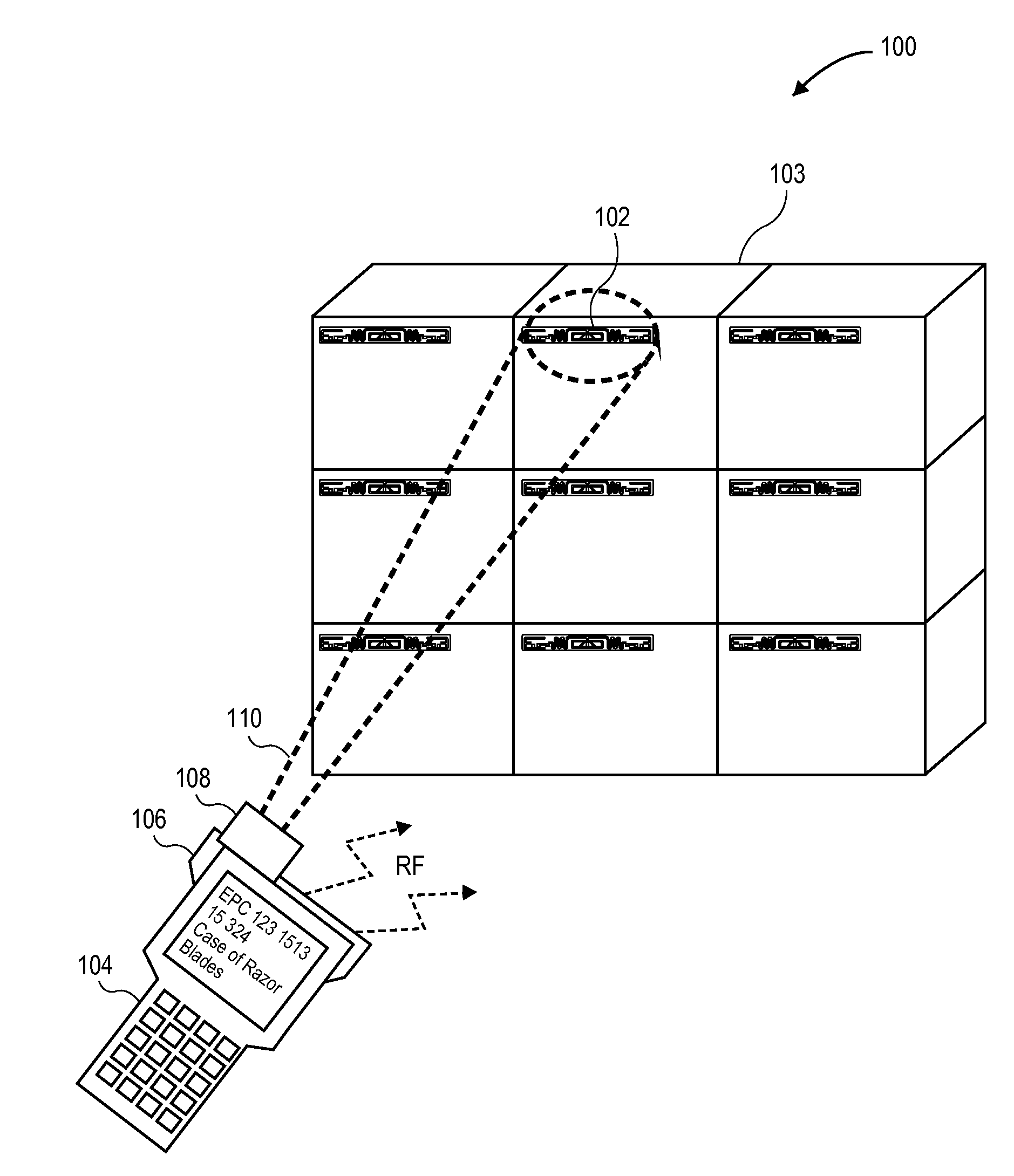
[0053]FIG. 1 illustrates a simplified block diagram of an RFID system 100 according to an embodiment of the present invention. In this example, tag 102 is attached to container 103 (e.g., box, corrugated box, carton, or the like). Tag 102 is in close proximity to other tags affixed to similar containers, such as on a densely packed pallet. Due to this proximity, handheld reader 104 using RF antenna 106 observes many tags in its RF field.

[0054]In ord...


PUM


Abstract

Methods and apparatuses for selecting a subset of RFID tags are provided in some embodiments. These methods and apparatuses utilize the susceptibility to light by persistent nodes found in passive tags. Light can be used to intentionally reduce persistence times in a particular subset tags or even an individual tag. Then, persistent nodes can be used as a selection criterion to distinguish previously illuminated tags from non-illuminated tags. In other embodiments, a power circuit receives a RF input source and generates a direct current (DC) output voltage. The circuit includes a bias circuit to supply a gate to source bias, which is independent of the DC output voltage. The circuit further includes a voltage multiplier circuit that is coupled to the bias circuit. The voltage multiplier circuit has MOS transistors with one transistor to receive the gate to source bias.

Description

[0001]This application is related to co-pending U.S. Provisional Patent Application No. 61 / 123,410, which was filed on Apr. 7, 2008; this application claims the benefit of the provisional's filing date under 35 U.S.C. §119(e) and is hereby incorporated herein by reference in its entirety.GOVERNMENT RIGHTS NOTICE[0002]Embodiments of the present invention were made with U.S. Government support under North Dakota State University Subcontract SPP002-5, Defense Microelectronics Activity (DMEA) Contract No. H94003-06-1-0601 (prime). Certain embodiments, including light insensitive circuit structures and transistor based voltage multipliers and demodulators described herein, were made with U.S. Government support under Defense Microelectronics Activity (DMEA) Contract No. H94003-06-1-0612. The U.S. Government has certain rights to this invention.FIELD OF THE TECHNOLOGY[0003]The present invention generally relates to the field of radio frequency identification (“RFID”) devices, and specific...

Claims


Application Information

Patent Timeline
Patent Type & Authority Applications(United States)
IPC IPC(8): G06K7/01H03K17/22G06K19/073
CPCG06K7/0008G06K7/10079G06K19/0701G06K7/10009G06K19/0728G06K19/07749G11C5/145G06K19/0723G06K19/073H02M7/217G06K19/077
Inventor HADLEY, MARK ALFREDATHERTON, JAMES HAROLDTU, JAYBOLING, EDWARD JOHNSMITH, JOHN STEPHEN
Owner RUIZHANG TECH LTD CO
Why Eureka
Try Eureka