Method for visualizing freeform surfaces by means of ray tracing

Active Publication Date: 2012-10-04
AUTODESK INC
View PDF6 Cites 6 Cited by
  • Summary
  • Abstract
  • Description
  • Claims
  • Application Information

AI Technical Summary

Benefits of technology

[0030]The use of a data structure for the bounding boxes, which data structure simultaneously contains specifications that uniquely identify and allow calculation of a surface fragment surrounded by the bounding box, is significantly less memory-intensive than previous methods and, at the same time, is faster in execution, while the same level of high image quality is maintained. This development for the first time allows the industry and other users to carry out a visualization directly from complex CAD data records, without needing to carry out the previously necessary and time-consuming “tessellation”.
[0031]A bounding box is preferably stored in a data structure having a number of bytes that is divisible by 16. This is advantageous for memory alignment because the arrangement in terms of addresses divisible by 16 in the main memory leads to efficient cache handling. The data structure preferably comprises 32 bytes. The advantage of this lies in the fact that all information describing the bounding box and, additionally, the grid coordinates can be stored in the data structure. Thus, the data structure may comprise the minimum values x_min, y_min and z_min of the bounding box and its maximum values x_max, y_max, z_max in 3D space, wherein each value can be specified by a 4 byte floating point number, and the grid coordinates y, z in each case as e.g. a 10 bit representation.
[0032]A hierarchic acceleration data structure may be placed over the bounding box, as described in O. Abert, 2009, “Augenblick—Ein effizientes Framework fur Echtzeit Ray Tracing” [“Sn

Problems solved by technology

This is largely based on the fact that physically plausible or correct simulations of shadows, refractions and similar light effects can only be simulated correctly by methods based on ray tracing.
However, this approximation is ever more error-prone as the number of triangles used to approximate the surface decreases.
However, this al

Method used


Image

  • Method for visualizing freeform surfaces by means of ray tracing
  • Method for visualizing freeform surfaces by means of ray tracing
  • Method for visualizing freeform surfaces by means of ray tracing

Examples


Example

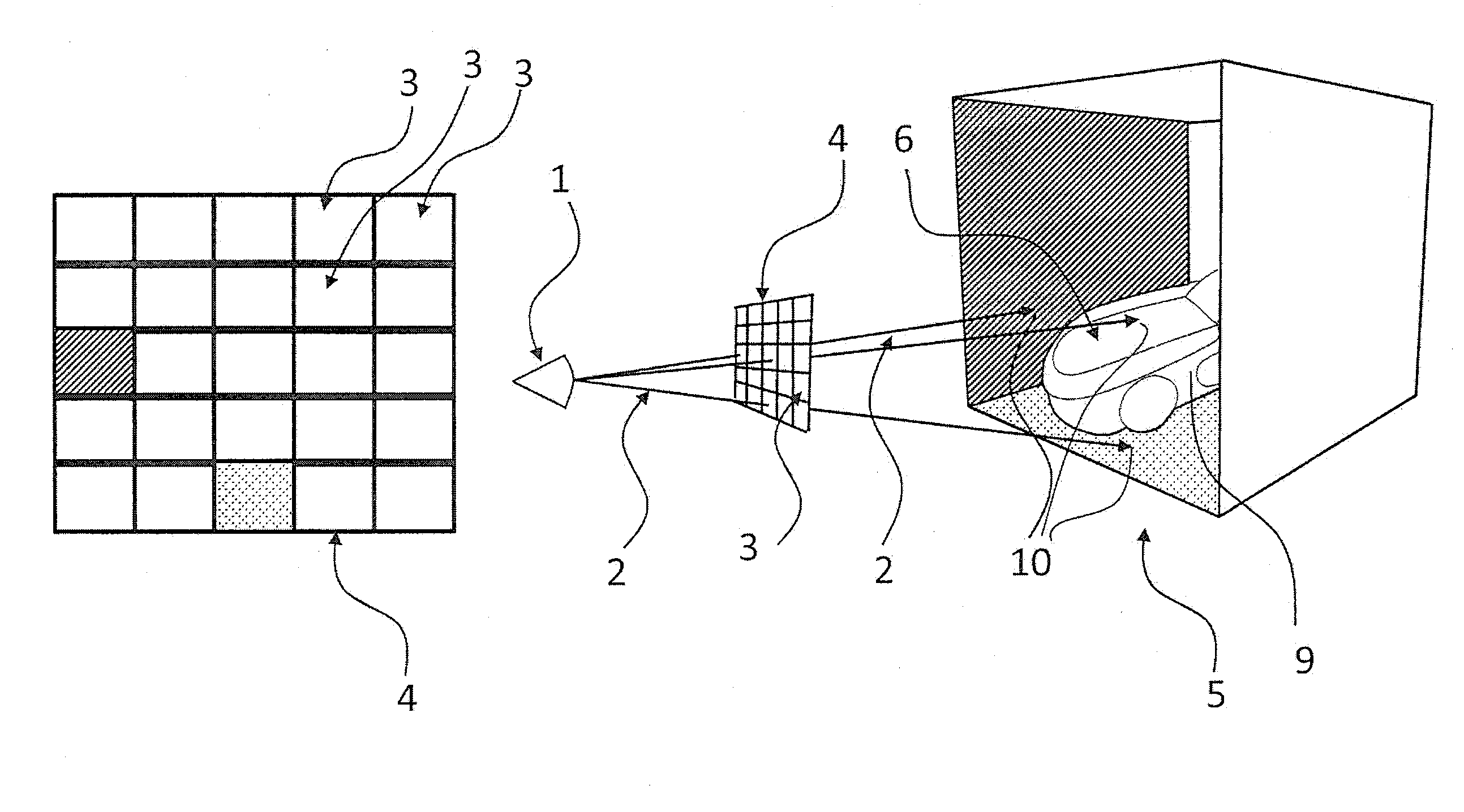
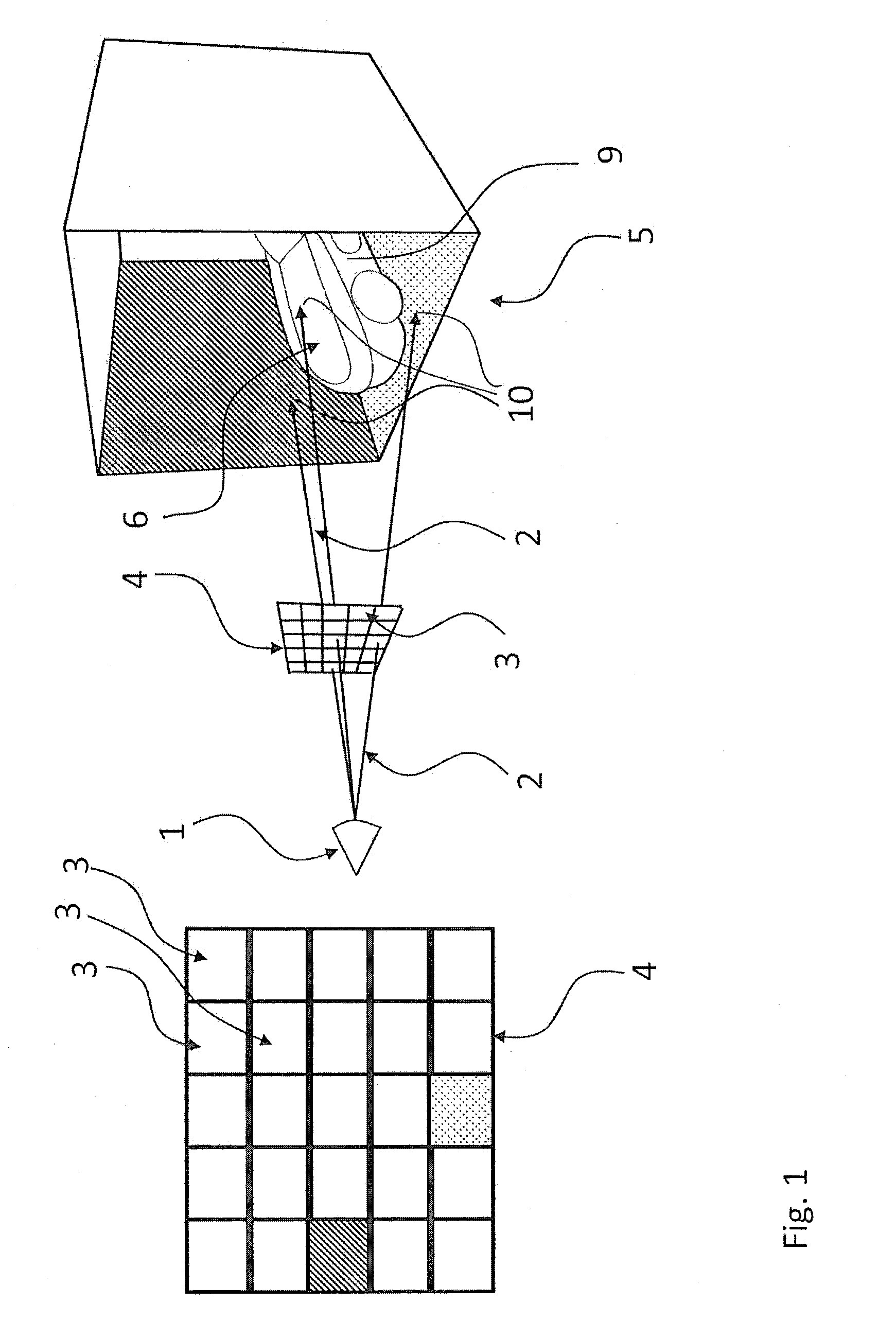
[0056]FIG. 1 shows a schematic illustration of the ray tracing principle for synthesizing a scene 5 as an image, for example with a resolution of 512×512 pixels 3. For simplicity, only 5×5 pixels 3 are illustrated in an image plane in FIG. 1. Here, virtual beams 2 are sent from a virtual camera 1 into a three-dimensional scene 5 through the pixels 3 in the virtual image plane 4, and said beams are made to intersect with the scene 5. At the intersections 10, illumination information and, from this, a color is determined and assigned to the respective pixel 3. Three beams 2 have been drawn in FIG. 1 in an exemplary fashion, which beams pass through three of the pixels 3 and impinge on the left sidewall, the floor of the scene 5 and on an object 9. Optionally further beams (not drawn in FIG. 1), so-called secondary beams, are emitted starting from the intersections 10, for example in order to simulate mirroring in or transparency of a surface. Those beams 2 that originate from the came...


PUM


Abstract

The invention relates to visualizing freeform surfaces, like NURBS surfaces, from three-dimensional construction data via Virtual beams from a virtual camera are sent out of a virtual image plane in a scene having at least one object and at least one freeform surface. Lighting values are calculated for each point where a beam intersects the freeform surface. The lighting values are then attributed to the pixels associated with the different points of intersection. The freeform surface is defined by two parameters (u, v), and related equations define all points of the surface of the freeform surface The subdivision of the freeform surface for determining the intersections with the beams based on the two parameters (u, v) is regular, so that the surface fragments form meshes of a two-dimensional grid of the freeform surface in the parameter space.

Description

CROSS-REFERENCE TO RELATED APPLICATIONS[0001]This application claims priority to German Patent Application No. 10 2011 015 893.6, filed Apr. 1, 2011, hereby incorporated herein by reference.SUMMARY OF THE INVENTION[0002]The invention relates to a method for visualizing freeform surfaces, more particularly NURBS surfaces, on a computer system from three-dimensional construction data by means of ray tracing, in which virtual beams are emitted into a scene from a virtual camera through respectively one pixel in a virtual image plane, which scene comprises at least one object with at least one freeform surface, and in which the intersection between each beam and the freeform surface is calculated and illumination values at these intersections are assigned to the pixels in the image plane, wherein the freeform surface is defined by an equation that is dependent on two parameters and describes all points on the surface of the freeform surface by inserting values for the parameters, and th...

Claims


Application Information

Patent Timeline
IPC IPC(8): H04N13/02
CPCG06T17/30G06T15/06G06T17/20G06T17/005G06T11/203
Inventor ABERT, OLIVER
Owner AUTODESK INC
Why Eureka
Try Eureka