Projection apparatus

a projection apparatus and projection technology, applied in the field of projection apparatuses, can solve the problems of more light loss, light loss, and light loss, and achieve the effect of improving the efficiency of light use of projection apparatus

Active Publication Date: 2012-10-04
YOUNG OPTICS
View PDF8 Cites 20 Cited by
  • Summary
  • Abstract
  • Description
  • Claims
  • Application Information

AI Technical Summary

Benefits of technology

[0009]Accordingly, the invention provides a projection apparatus in which an illumination beam is shaped ...

Problems solved by technology

As a result, light loss is caused.
In this way, when the light beam enters the lens cell at an angle greater than the valid light collection angle of the lens cells, than the travel direction of the light beam deviates from the DMD ...

Method used


Image

  • Projection apparatus
  • Projection apparatus
  • Projection apparatus

Examples


first embodiment

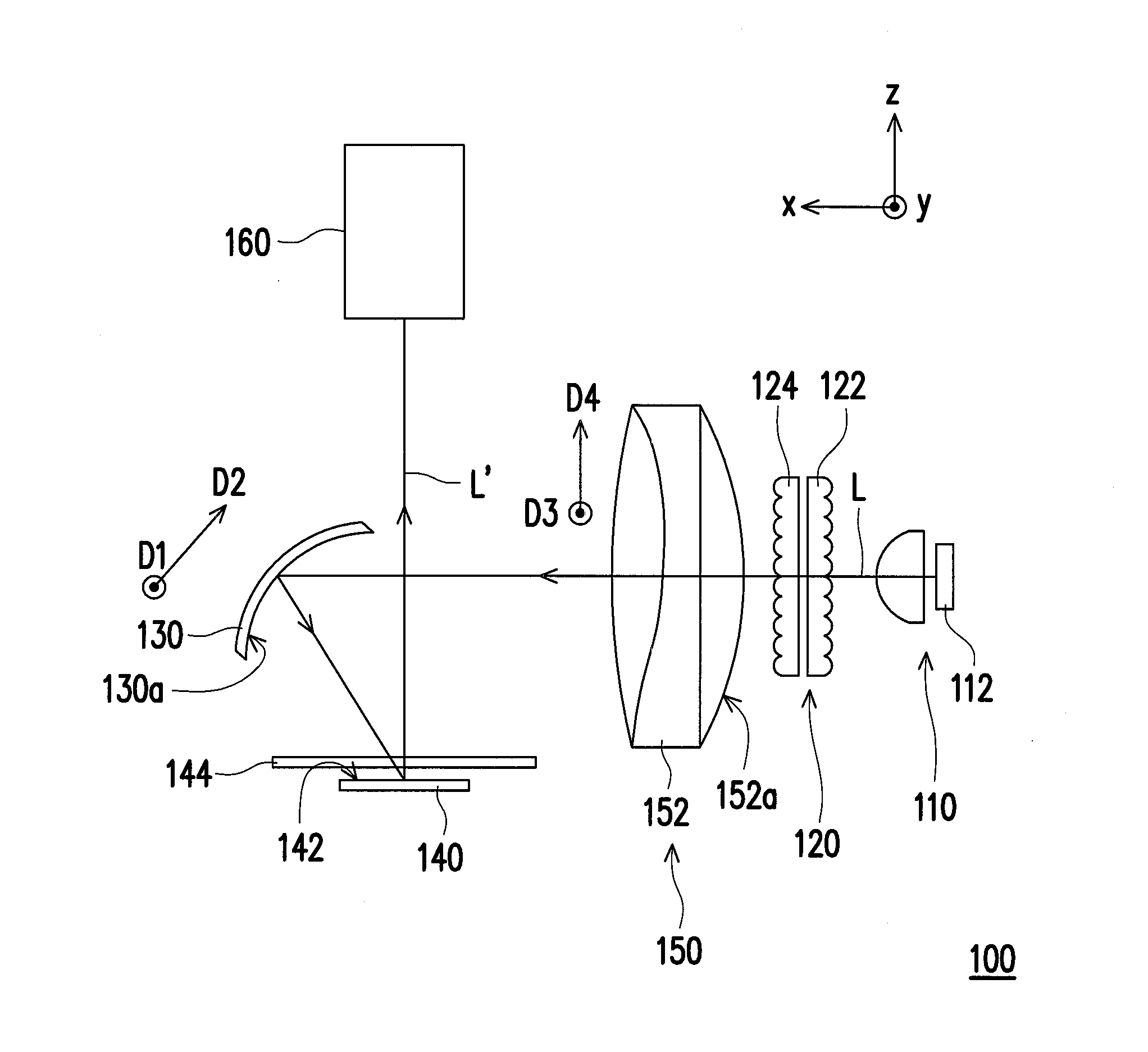
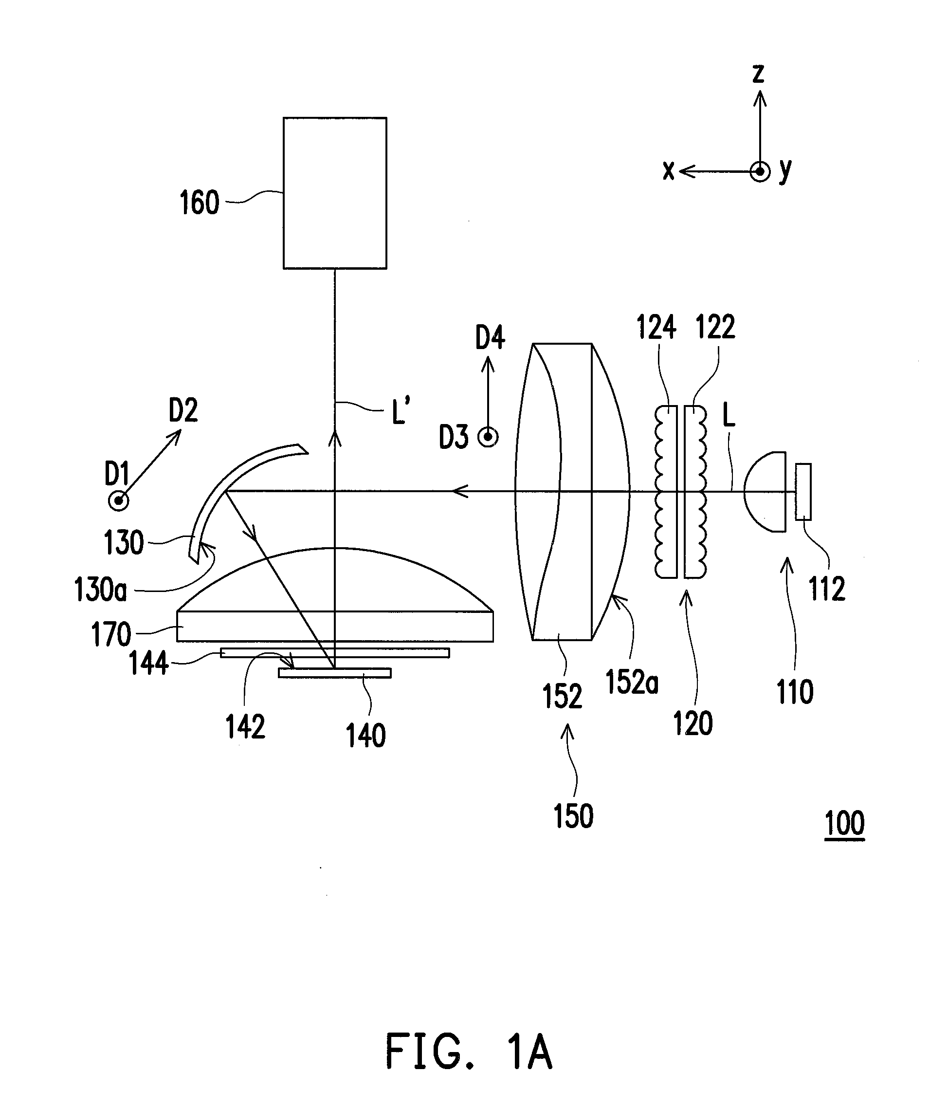
[0051]FIG. 1A is a top view of a projection apparatus according to the first embodiment of the invention. Referring to FIG. 1A, the projection apparatus 100 in the embodiment includes a light source 110, a light uniforming device 120, a first curved-surface reflection device 130, and a light valve 140.

[0052]The light source 110 in the embodiment is configured to provide an illumination beam L. In the embodiment, the light source 110 may include a rectangular light emitting diode (LED) chip 112. However, the invention is not limited thereto, and in other embodiments, the light source 110 may also be a LED chip array or a high pressure mercury lamp.

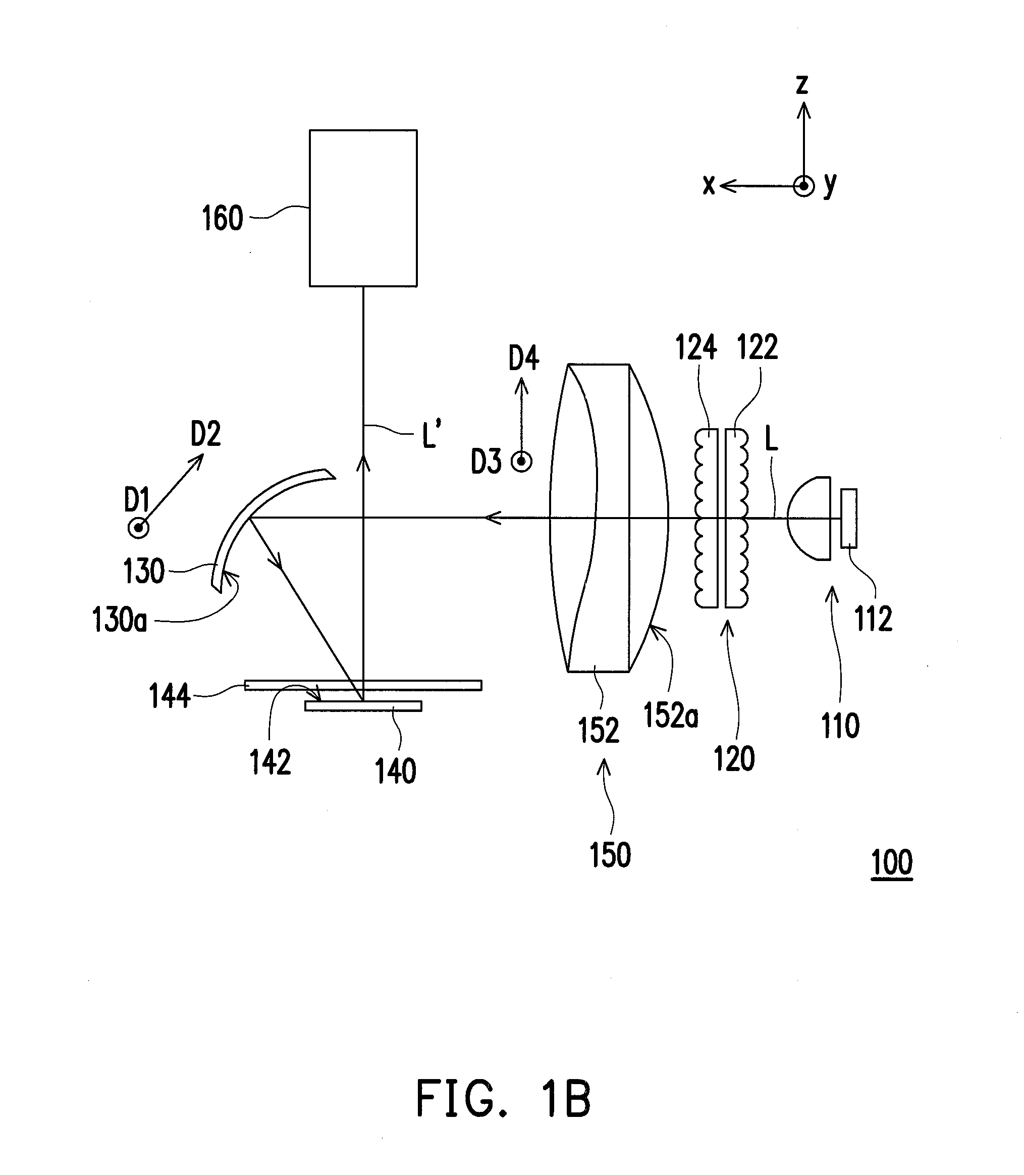
[0053]FIG. 1B is a top view of a projection apparatus according to another embodiment of the invention. The projection apparatus in FIG. 1B is approximately the same as the projection apparatus 100 in FIG. 1A except the field lens. In the embodiment, no field lens is placed in front of the light valve 140.

[0054]Part (a) of FIG. 2A is a fron...

second embodiment

[0068]FIG. 3 is a top view of a projection apparatus 100A according to the second embodiment of the invention. Referring to FIG. 3, the projection apparatus 100A in the embodiment is similar to the projection apparatus 100 in the first embodiment, and the difference between the two is that the projection apparatus 100A in the embodiment includes a relay lens 180. The relay lens 180 allows the illumination beam L to be led to the first curved-surface reflection device 130. Besides, the lens arrays 122 and 124 in the embodiment can be integrally formed.

third embodiment

[0069]FIG. 4 is a top view of a projection apparatus 100B according to the third embodiment of the invention. Referring to FIG. 4, the projection apparatus 100B in the embodiment is similar to the projection apparatus 100A in the second embodiment, and the difference between the two is that the projection apparatus 100B in the embodiment further includes a reflection device 190, wherein the reflection device 190 may be a mirror. In addition, in the projection apparatus 100B of the embodiment, the first curved-surface reflection device 130 is disposed at a different position as that in the projection apparatus 100A of the second embodiment.

[0070]To be specific, in the embodiment, the first curved-surface reflection device 130 is on the optical paths between the light uniforming device 120 and the relay lens 180. The reflection device 190 is on the optical paths between the relay lens 180 and the light valve 140, wherein the reflection device 190 reflects the illumination beam L emitt...


PUM


Abstract

A projection apparatus including a light source, a light valve, a light uniforming device, and a first curved-surface reflection device is provided. The light source provides an illumination beam. The light valve is disposed on a transmission path of the illumination beam for converting the illumination beam into an image beam. The light valve has an active surface that substantially has a rectangular contour. The light uniforming device is disposed on the transmission path of the illumination beam and between the light source and the light valve. The first curved-surface reflection device is disposed on the transmission path of the illumination beam and between the light source and the light valve for reflecting the illumination beam to the light valve. A curvature of the first curved-surface reflection device along a first direction is not equal to a curvature of the first curved-surface reflection device along a second direction.

Description

CROSS-REFERENCE TO RELATED APPLICATION[0001]This application claims the priority benefit of Taiwan application serial no. 100111299, filed Mar. 31, 2011. The entirety of the above-mentioned patent application is hereby incorporated by reference herein and made a part of this specification.BACKGROUND OF THE INVENTION[0002]1. Field of the Invention[0003]The invention generally relates to a projection apparatus, and more particularly, to a projection apparatus with improved light use efficiency.[0004]2. Description of Related Art[0005]Generally speaking, a conventional projection apparatus includes two lens arrays and a digital micro-mirror device (DMD). Each of the lens arrays includes a plurality of lens cells, and the lens cells in the two lens arrays are respectively corresponding to each other. A light beam can be led to the DMD by the lens cells in the lens arrays so that a light spot is shaped and uniformed. However, because the DMD in a conventional projection apparatus has a r...

Claims


Application Information

Patent Timeline
IPC IPC(8): G03B21/28
CPCG03B21/2013G03B33/06G03B21/208G03B21/2066G02F1/29G02F1/292G02F1/293G02F1/2955G03B21/28
Inventor CHEN, YU-POCHEN, S-WEI
Owner YOUNG OPTICS
Why Eureka
Try Eureka