Imaging lens

a technology of spherical aberration and lens, applied in the field of imaging lenses, can solve the problems of difficult to reduce costs, difficult to realize both the miniaturization and the aberration correction, and achieve the effects of small and high-performance, favorable correction of spherical aberration, and weak

Active Publication Date: 2012-10-04
TOKYO VISIONARY OPTICS CO LTD
View PDF1 Cites 22 Cited by
  • Summary
  • Abstract
  • Description
  • Claims
  • Application Information

AI Technical Summary

Benefits of technology

[0012]An advantage of the present invention is to obtain an imaging lens for solid-state image sensors that is small and high-performance, as well as low-cost.
[0013]An imaging lens for use in solid-state image sensors according to an aspect of the present invention includes: an aperture stop; a biconvex first lens directing convex surfaces toward an object side and an image side; a second lens directing a convex surface toward the object side near an optical axis and having negative refractive power; a biconvex third lens directing convex surfaces toward the object side and the image side near the optical axis; a fourth lens directing a concave surface toward the object side near the optical axis and having positive refractive power; and a fifth lens directing a convex surface toward the object side near the optical axis and having negative refractive power. The aperture stop and the first to fifth lenses are arranged in this order from the object side of the imaging lens, and a conditional expression 1 is satisfied, the conditional expression 1 being 0.50<f1 / f<0.76 where f1 represents the focal length of the first lens and f represents the focal length of the entire imaging lens.
[0014]In the above-mentioned configuration, the first and second lenses broadly generates required power and corrects chromatic aberration, and the third to fifth lenses mainly correct coma aberration, astigmatism, and field curvature. Since the second lens is formed into a meniscus shape where a convex surface is directed toward the object side near the optical axis, spherical aberration is favorably corrected. Further, since the third lens is formed into a biconvex shape where convex surfaces are directed toward the object side and the image side surface near the optical axis and has weak power so as to suppress influence on the power of the entire imaging lens, off-axis aberrations (in particular, coma aberration and field curvature) are favorably corrected. Further, the disposition of the aperture stop on the object side of the first lens facilitates control of the chief ray angle (CRA). That is, image sensors, which are required to be telecentric, easily control the incident angle of light beams and secure a sufficient light amount on the periphery having a small amount of light. Further, since the shapes and refractive power of the lenses are optimally balanced, a small, high-performance imaging lens is realized.
[0015]The conditional expression 1 defines the focal length of the first lens relative to that of the entire imaging lens. Confining the focal length of the first lens within the range of the conditional expression 1 can favorably correct spherical aberration and coma aberration while reducing the total optical length.
[0016]Exceeding the upper limit “0.76” of the conditional expression 1 weakens the power of the first lens excessively and increases the total optical length. This makes miniaturization difficult. Falling below the lower limit “0.50” strengthens the power of the first lens excessively. This is advantageous to miniaturization but makes it difficult to correct spherical aberration and coma aberration.
[0017]In the imaging lens having the above-mentioned configuration, both surfaces of the third lens are preferably aspheric, and a conditional expression 2 is preferably satisfied, the conditional expression 2 being −0.80<(r5+r6) / (r5−r6)<0.55 where r5 represents the curvature radius of an object side surface of the third lens and r6 represents the curvature radius of an image side surface thereof.

Problems solved by technology

While the above-mentioned imaging lenses according to Patent Documents 1 to 3 include five lenses to increase performance, their long total lengths make it difficult to realize both their miniaturization and favorable aberration correction.
The use of glass material also makes it difficult to reduce the cost.

Method used


Image

  • Imaging lens
  • Imaging lens
  • Imaging lens

Examples


example 1

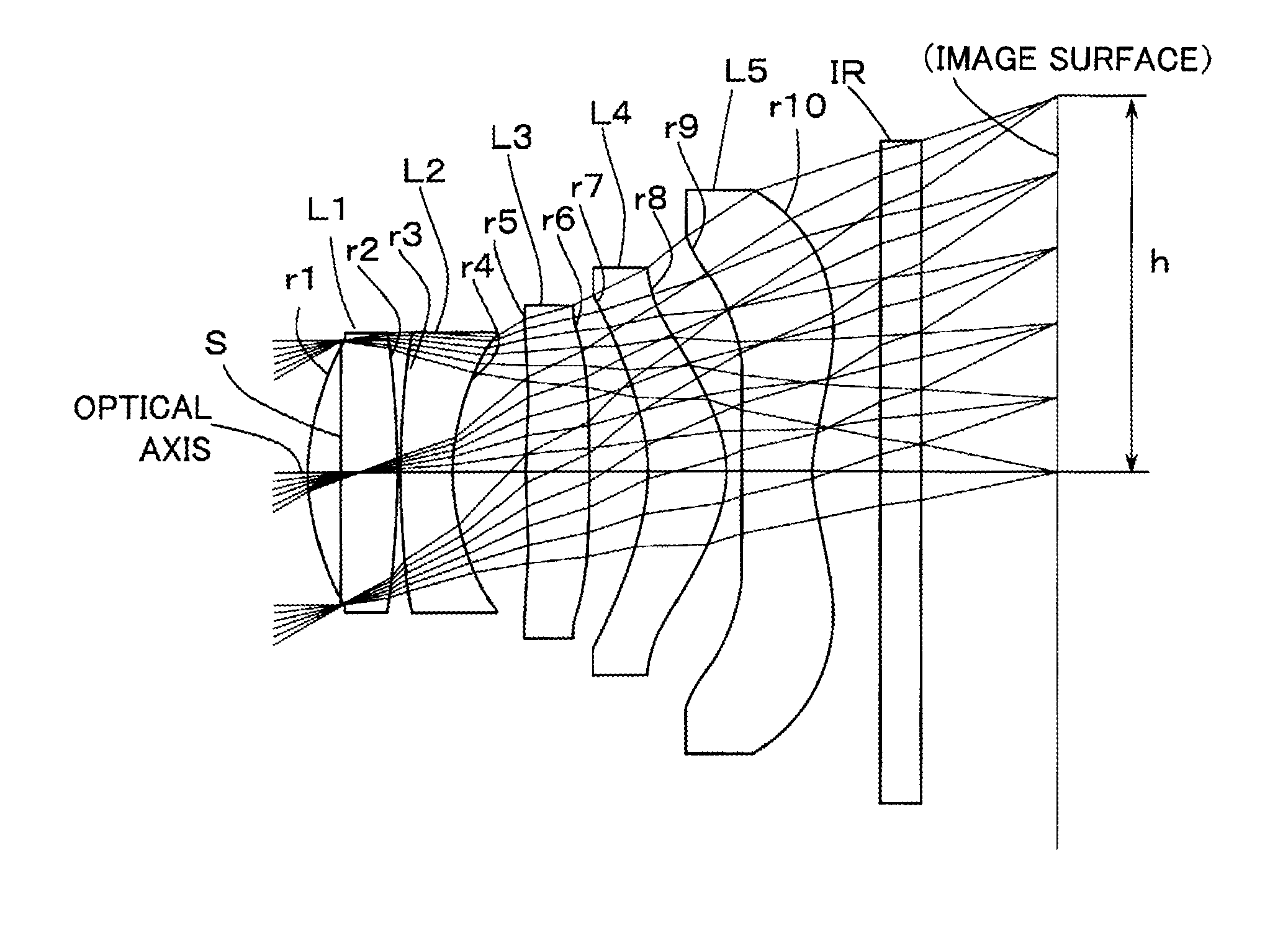
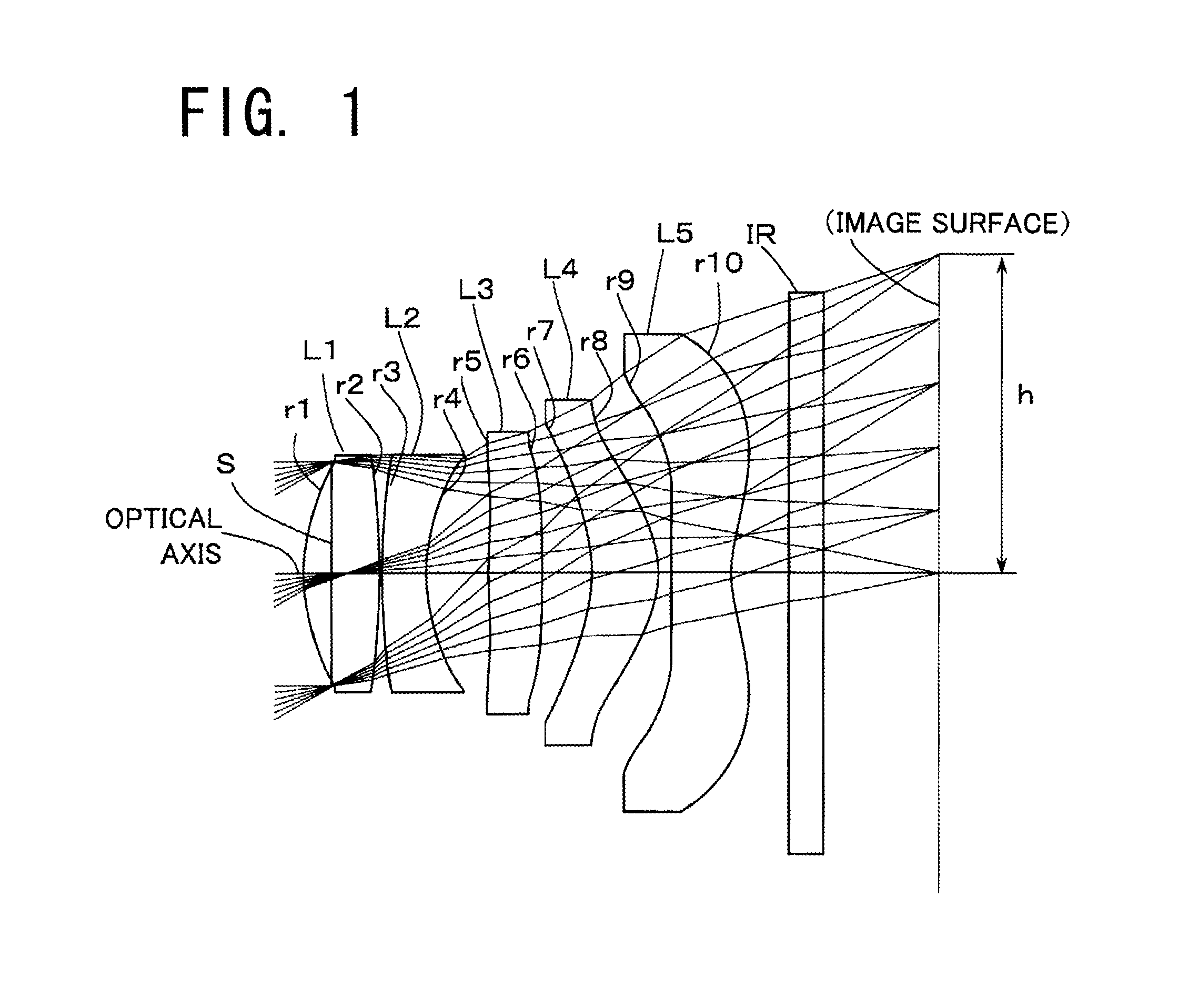
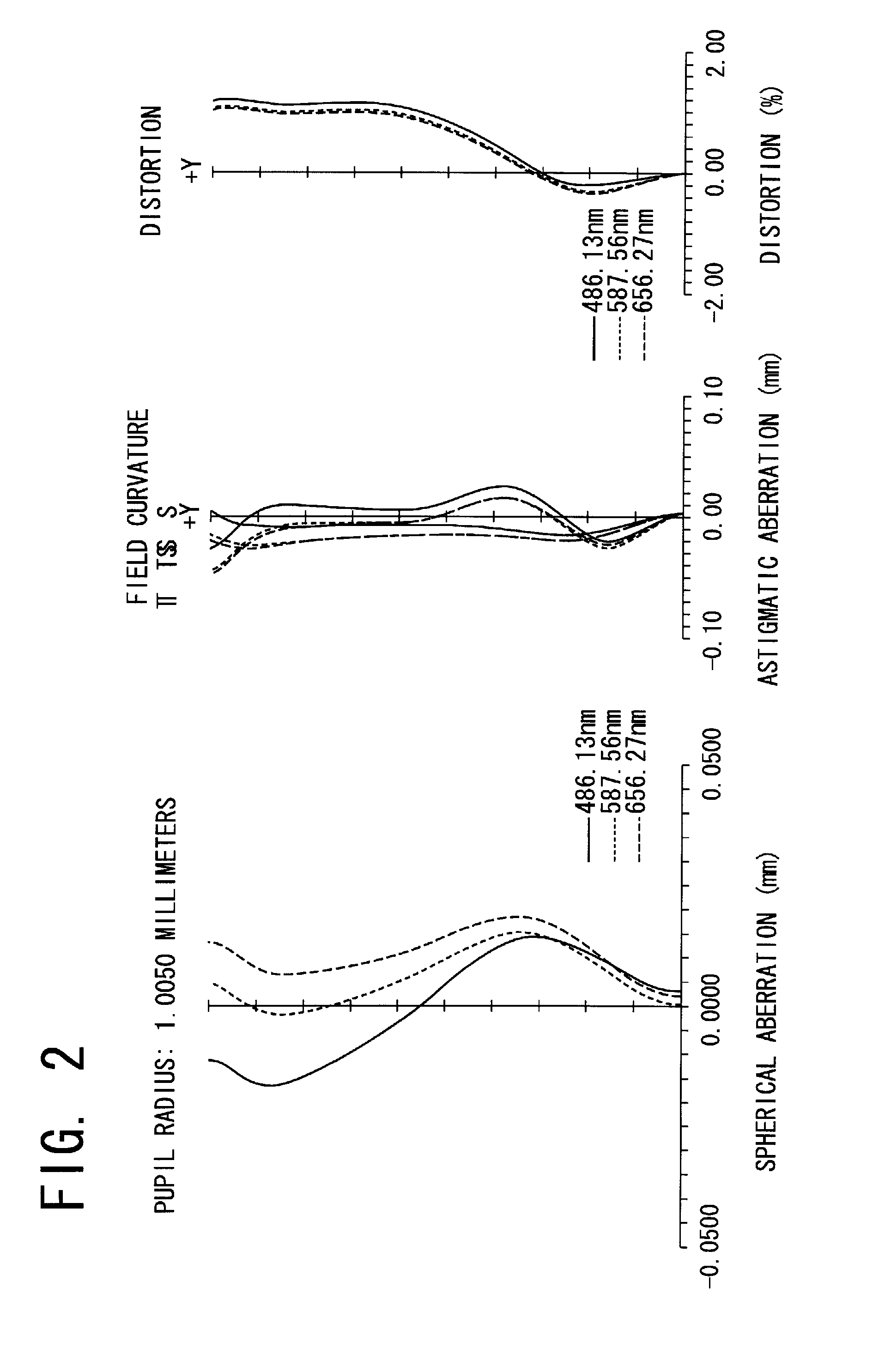
[0051]Basic data about the imaging lens according to Example 1 is shown in Table 1.

TABLE 1f = 4.831 Fno = 2.404 ω = 30.52°iRdNdνdS (aperture stop)∞−0.2451*1.9220.67191.534656.22*−5.1670.0233*7.0380.3871.614225.64*1.6200.5565*8.5030.4691.534656.26*−50.0000.43957*−1.7210.591.534656.28*−0.9730.129*11.9400.53281.534656.210* 1.3870.511 ∞0.31.516864.212 ∞1.004IMA∞ikA4A6A8A10A12A141*−9.000E−01  1.430E−02−1.080E−02    5.887E−03−2.142E−03  −1.326E−03−3.454E−03  2*−1.047E+02  9.432E−031.860E−02−3.020E−02−1.020E−02    7.164E−03−1.107E−03  3*  1.480E+01−2.200E−026.650E−02−5.380E−021.540E−03−8.125E−055.368E−034*−5.590E−01−1.289E−011.729E−01−1.069E−013.120E−02−3.246E−033.809E−035*−3.000E+02−4.320E−02−2.420E−02    1.130E−026.194E−03  3.310E−03−6.472E−04  6*  0.000E+00−8.460E−025.240E−02−4.560E−021.720E−02−6.281E−046.879E−047*  4.100E−01  3.590E−028.680E−02−5.010E−021.410E−02−4.669E−040.000E+008*−2.797E+00−1.370E−02−5.428E−03    2.020E−02−3.985E−03  −6.448E−041.466E−049*   1.4901E+01−7.790E−02−6.99...

example 2

[0056]Basic data about the imaging lens according to Example 2 is shown in Table 2.

TABLE 2f = 1.30 Fno = 2.80 ω = 33.72°iRdNdνdS (aperture stop)∞−0.141*1.9140.81.534656.22*−4.5500.03163*13.5320.3411.614225.64*2.0040.4875*50.0000.4611.534656.26*−15.2740.2317*−2.3090.661.534656.28*−1.1550.039*70.0001.061.534656.210* 1.5310.3811 ∞0.31.516864.212 ∞0.622IMA∞ikA4A6A8A10A12A141*−1.050E+00    2.815E−031.440E−02−3.030E−020.000E+000.000E+000.000E+002*0.000E+00  4.410E−02−7.010E−02    3.583E−030.000E+000.000E+000.000E+003*−4.100E+01  −2.050E−025.170E−02−7.660E−023.520E−020.000E+000.000E+004*0.000E+00−9.620E−021.891E−01−1.906E−011.289E−01−3.430E−02  0.000E+005*1.470E+02−9.320E−02−2.630E−02    4.700E−02−1.860E−02  1.190E−020.000E+006*0.000E+00−7.150E−021.610E−02−3.810B−021.320E−025.080E−030.000E+007*1.380E+00  6.860E−021.840E−02−3.500E−029.312E−032.952E−030.000E+008*−2.700E+00  −3.830E−021.520E−02  1.210E−02−7.534E−03  1.282E−030.000E+009*0.000E+00−9.020E−021.266E−02  3.429E−03−9.405E−04  0.000E...

example 3

[0060]Basic data about the imaging lens according to Example 3 is shown in Table 3.

TABLE 3f = 3.409 Fno = 2.550 ω = 39.996°iRdNdνdS (aperture stop)∞−0.121*1.5860.5181.534656.22*−6.1030.0383*8.8510.281.614225.64*1.7590.33145*8.3480.39451.534656.26*66.0000.3367*−2.0680.43671.534656.28*−0.9080.2559*23.6730.531.534656.210* 1.0890.3811 ∞0.31.516864.212 ∞0.391IMA∞ikA4A6A8A10A12A141*−1.000E+00  5.821E−032.220E−02−1.435E−010.000E+000.000E+000.000E+002*  0.000E+00  7.423E−03−1.152E−01  −2.403E−030.000E+000.000E+000.000E+003*−1.680E+02−3.130E−023.670E−02−5.950E−021.349E−010.000E+000.000E+004*  0.000E+00−9.610E−021.910E−01−1.769E−011.600E−01−3.130E−02  0.000E+005*−9.400E+01−9.200E−026.268E−03  4.880E−02−3.860E−02  2.407E−040.000E+006*  0.000E+00−8.910E−023.784E−03−2.820E−021.800E−026.949E−030.000E+007*  1.170E+00  7.550E−026.515E−03−3.460E−021.210E−024.966E−030.000E+008*−2.865E+00−2.270E−022.790E−02  1.540E−02−8.151E−03  6.265E−040.000E+009*  0.000E+00−9.070E−028.390E−03  3.833E−03−5.748E−04  ...


PUM


Abstract

An imaging lens includes: an aperture stop; a biconvex first lens directing convex surfaces toward an object and an image; a second lens directing a convex surface toward the object near the optical axis and having negative refractive power; a biconvex third lens directing convex surfaces toward the object and the image near the optical axis; a fourth lens directing a concave surface toward the object near the optical axis and having positive refractive power; and a fifth lens directing a convex surface toward the object near the optical axis and having negative refractive power. The aperture stop and the first to fifth lenses are arranged in this order from the object side, and a conditional expression 1 being 0.50<f1 / f<0.76 is satisfied, where f1 represents the focal length of the first lens and f represents the focal length of the entire imaging lens.

Description

[0001]The present application is based on and claims priority of Japanese patent application No. 2011-074109 filed on Mar. 30, 2011, the entire contents of which are hereby incorporated by reference.BACKGROUND OF THE INVENTION[0002]1. Field of the Invention[0003]The present invention relates to an imaging lens for solid-state image sensors for use in small imaging devices for use in small, thin electronic apparatuses such as mobile terminals, including cellular phones and mobile game machines, and personal digital assistants (PDAs).[0004]2. Description of the Related Art[0005]As the market for mobile terminals including an imaging device expands in recent years, a miniaturized solid-state image sensor having a high pixel number has been mounted on such imaging devices.[0006]With such miniaturization and pixel number increase of image sensors, imaging lenses have been required to achieve higher performance such as higher resolution and higher image quality. Further, with their widesp...

Claims


Application Information

Patent Timeline
Patent Type & Authority Applications(United States)
IPC IPC(8): G02B9/60
CPCG02B13/0045
Inventor HASHIMOTO, MASAYA
Owner TOKYO VISIONARY OPTICS CO LTD
Why Eureka
Try Eureka