Dust collector

A dust collection device and dust technology, applied in the direction of dust removal, cleaning methods and utensils, chemical instruments and methods, etc., can solve the problem of high replacement cost of filter bodies

Inactive Publication Date: 2008-04-09
ANLET CO LTD
View PDF4 Cites 32 Cited by
  • Summary
  • Abstract
  • Description
  • Claims
  • Application Information

AI Technical Summary

Problems solved by technology

Although this dust collector prevents dust from adhering to other filters when the filter is cleaned, it cannot be denied that the replacement cost of the filter body becomes high due to the use of multiple filter units.

Method used


Image

  • Dust collector
  • Dust collector
  • Dust collector

Examples


no. 1 approach

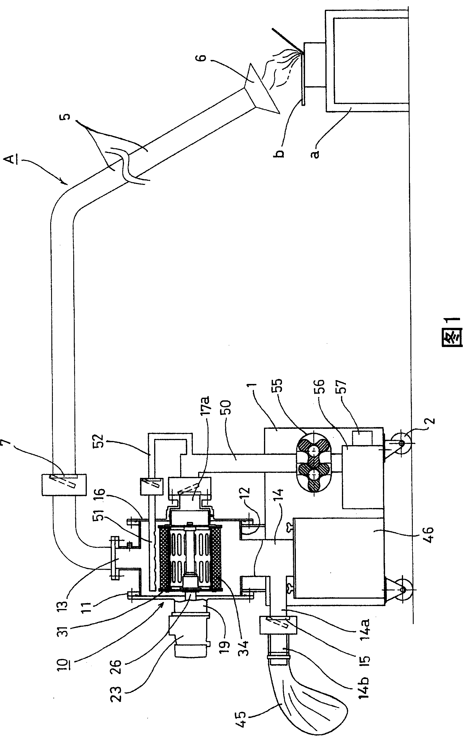
[0040] As shown in FIG. 1 , the dust collecting device A of the first embodiment is composed of a collection unit 10 and a Roots-type blower 55, and the collection unit 10 makes viscous dust generated by welding, dust generated by a grinding machine, etc. The mist and dust are sucked together with the surrounding air by the suction cover 6 arranged at the front end of the suction pipe 5 to collect the mist and dust. The Roots blower 55 makes the housing 11 of the collection unit 10 The air passing through the unit is discharged to the outside while the inside becomes negative pressure, and the collecting unit 10 and the Roots blower 55 are installed on a frame 1 having rollers 2 . 7 is a check valve installed on the suction pipe 5 .

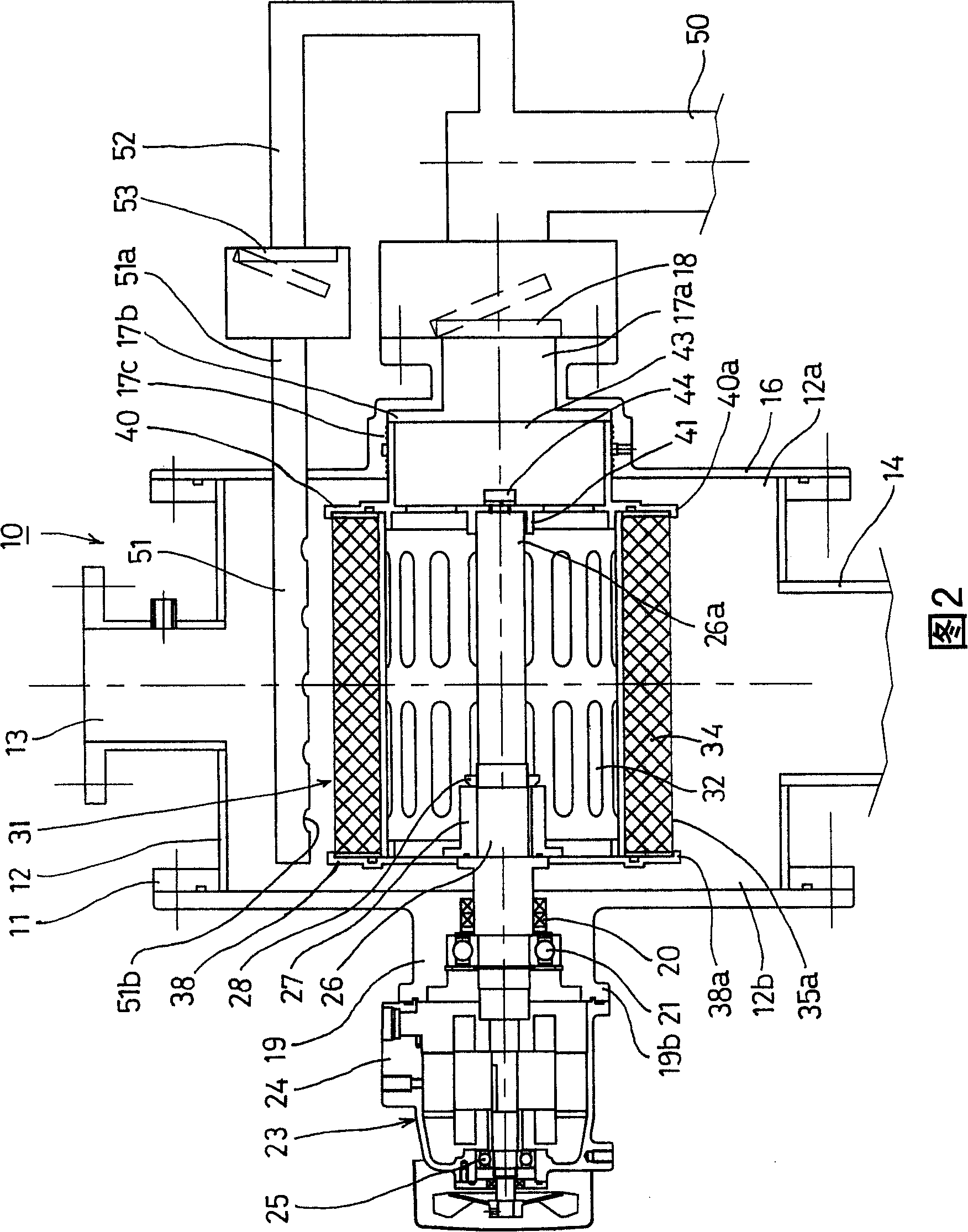
[0041] The housing 11 of the trapping unit 10 is composed of a cylindrical housing main body 12 , an end cover 16 and a frame 19 . The end cap 16 is provided with an outflow port 17 a having a check valve 18 and is attached to the opening end 12...

no. 2 approach

[0085] FIG. 10 shows the dust collector B of the second embodiment. The main structure of the dust collector B is the same as that of the dust collector A of the above-mentioned first embodiment.

[0086] The dust collector B is composed of a collection unit 110 and a Roots-type blower 160. The collection unit 110 makes fine dust such as flour, plastic, paper, wood and other non-viscous light dust class together with the surrounding air by the air. The suction hood 106 arranged at the front end of the suction pipe 105 sucks and collects the dust; the Roots blower 160 turns the inside of the housing 111 of the collection unit 110 into a negative pressure, and makes the dust passing through the unit The air is exhausted to the outside, and the capturing unit 110 and the Roots blower 160 are provided on the vehicle frame 101 having the rolling wheels 102 . 107 is a check valve attached to the suction pipe 105 .

[0087] The housing 111 of the trapping unit 110 is composed of a ...


PUM


Abstract

A dust collector includes a collection unit including a suction pipe and a Roots blower outwardly discharging the air having passed through the collection unit. The collection unit further includes a rotational shaft rotatably mounted in a housing of the case and disposed so as to face an interior of the case, a rotary filter mounted on the shaft and including a cylindrical porous core and a filter material attached to an outer circumference of the core and having a number of folds made of nonwoven cloth with a mesh into a continuous zigzag shape, an air blower nozzle blowing on an outer surface of the rotary filter pressure air produced by drive of the blower in a reverse direction thereby to clean the filter, and a recovery bag accommodating the dust or the like removed from the rotary filer during cleaning by the air blower nozzle.

Description

technical field [0001] The present invention relates to fumes (fume) generated during arc welding operations, fine dust and mist (mist) generated by cutting machines, grinding machines, etc., carbon powder (carbon) generated when road sweepers clean roads, Dust collectors for collecting and recovering oil and dust, fine dust generated in the process of producing edible materials such as flour, and non-sticky light dust generated in the processing of plastics, paper, and wood Object dust collection device. Background technique [0002] (1) When arc welding a welding iron material coated with antirust oil or paint, fine fume of 100 angstrom level or viscous fine fume of 0.01 μm to 1 μm is generated. In general filter-type dust collectors, although filters with meshes of 0.1 μm to 0.5 μm are used, clogging of the meshes tends to occur. Therefore, a dust recovery method has been developed in which a mixture in which lime powder and the like are mixed in compressed air generate...

Claims


Application Information

Patent Timeline
Patent Type & Authority Applications(China)
IPC IPC(8): B08B15/04
Inventor 横井康名加藤利明竹田昌史伊藤义展
Owner ANLET CO LTD
Why Eureka
Try Eureka