Hybrid permanent/reversible dynamic range control system

a dynamic range control and permanent technology, applied in gain control, electrical transducers, instruments, etc., can solve the problems of viewer or listener complaints, unfavorable consumer environments for large variations in loudness or dynamic range,

Active Publication Date: 2012-10-04
AUDYNE
View PDF3 Cites 46 Cited by
  • Summary
  • Abstract
  • Description
  • Claims
  • Application Information

AI Technical Summary

Problems solved by technology

In some cases these program and commercial elements can differ substantially in average loudness and dynamic range and many consumer environments are not conducive to these large variations in loudness or dynamic range.
Artistic intent while perhaps appropriate in more carefully controlled situations can cause audibility problems and result in viewer or listener complaints.
This is commonly referred to as the “loud commercial problem” but can be caused as much by excessive dynamic range as mismatched loudness.

Method used


Image

  • Hybrid permanent/reversible dynamic range control system
  • Hybrid permanent/reversible dynamic range control system
  • Hybrid permanent/reversible dynamic range control system

Examples


Embodiment Construction

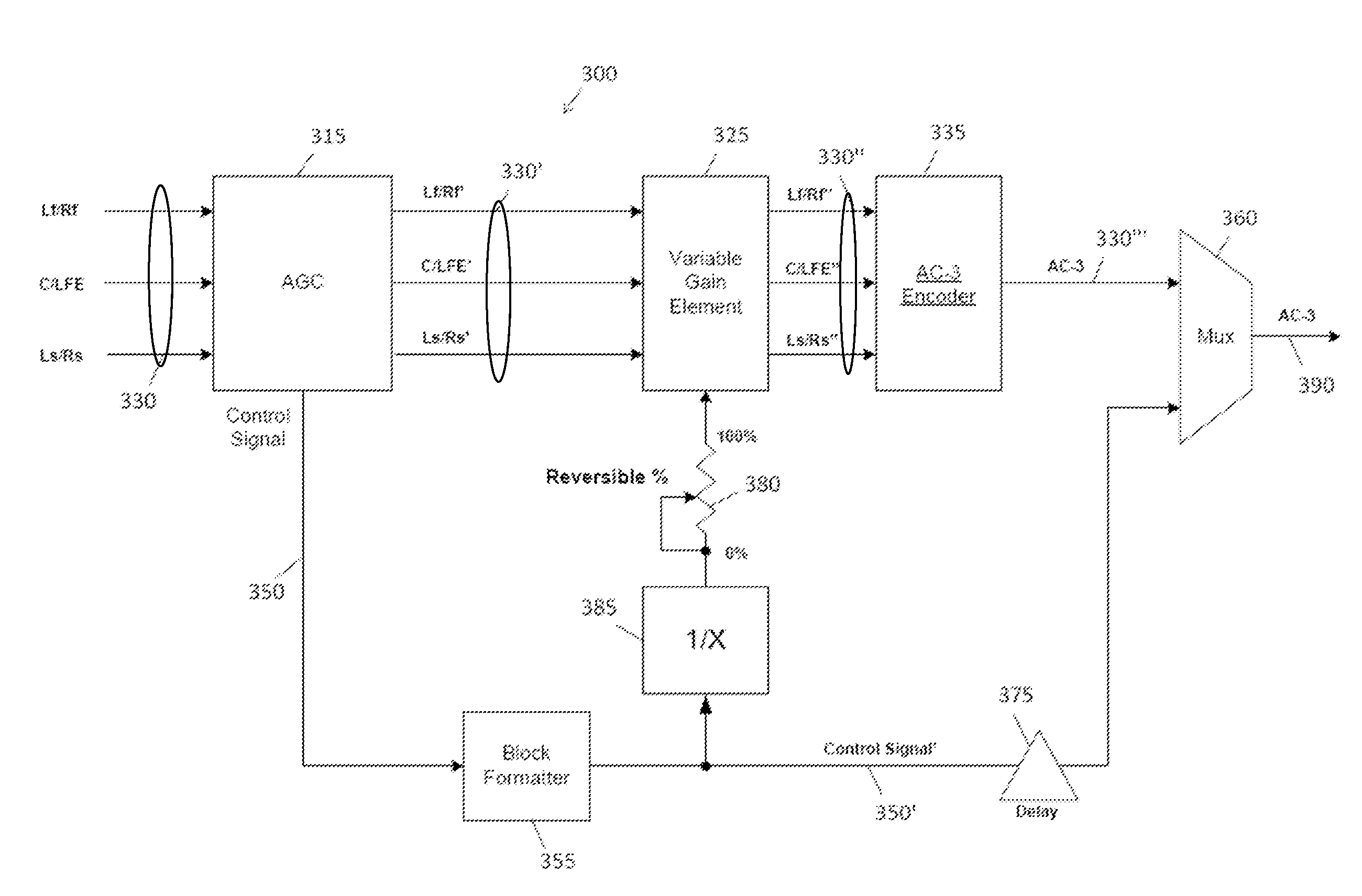
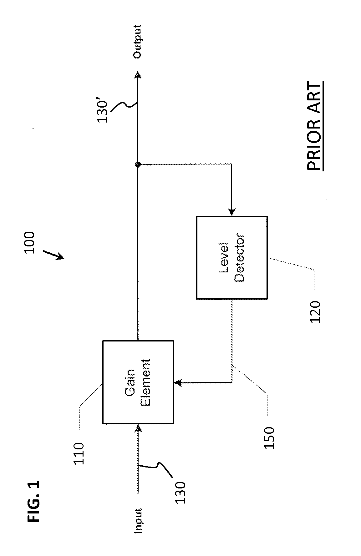
[0042]Dynamic range of an applied audio signal can be directly and permanently adjusted by detecting the level of the audio signal and generating a control signal that is used to adjust the gain of the audio higher if it is lower than some reference or to adjust the gain of the audio signal lower if it is higher than some reference, a process commonly known as Automatic Gain Control (AGC).

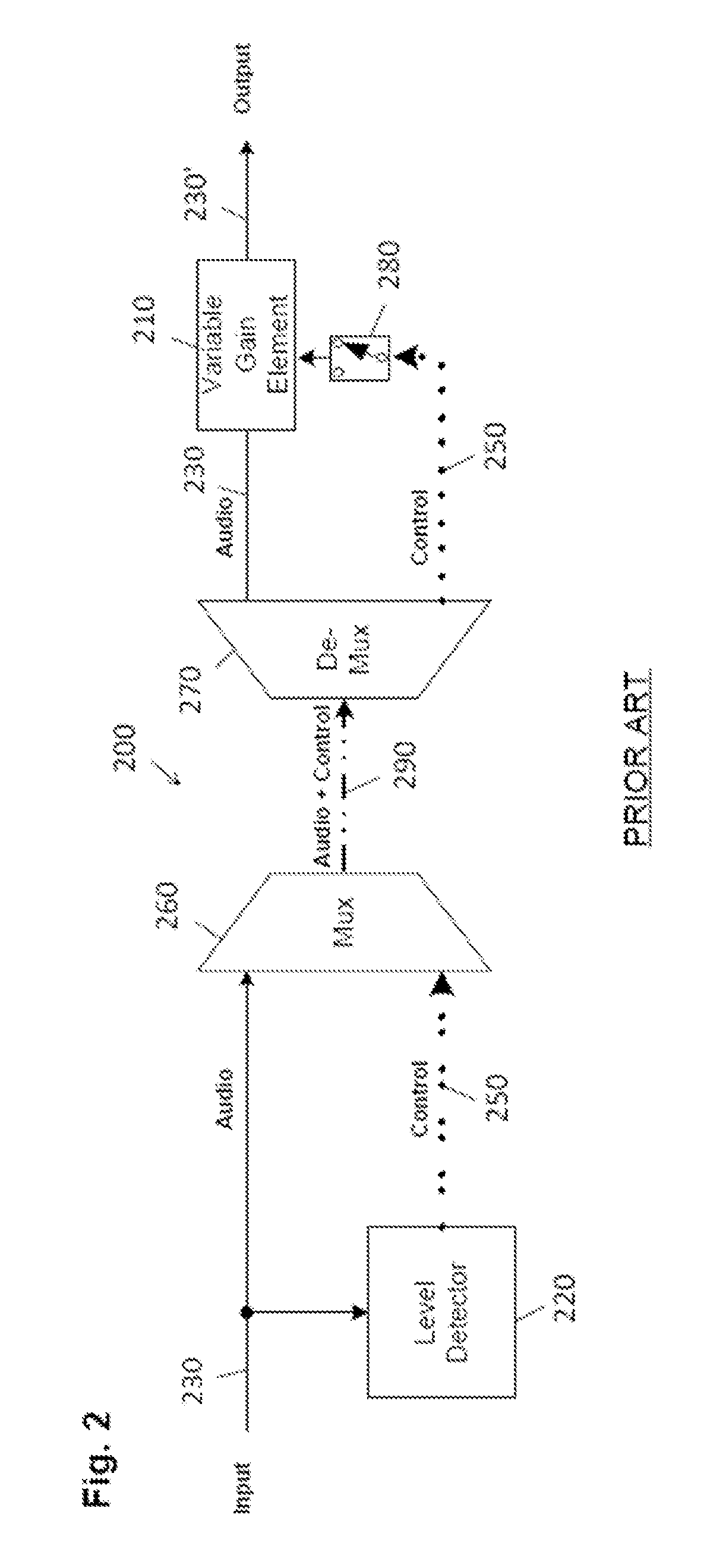
[0043]Dynamic range of an applied audio signal can also be adjusted by detecting the level of the audio signal and generating a control signal that is passed as metadata along with the original audio to some receiving or decoding device where the control signal can be applied directly to adjust the gain of the audio higher if it is lower than some reference or to adjust the gain of the audio signal lower if it is higher than some reference. This control signal can also be scaled before application to produce less or more control of the audio signal, or the control signal can be ignored thus resulti...


PUM


Abstract

A system for controlling dynamic range of an audio signal comprises an automatic gain control element that receives an input signal having a varying level and outputs a control signal that varies based on the varying level of the input signal and a modified input signal having a dynamic range different than a dynamic range of the input signal. The system also comprises an inverter that inverts the control signal or a block-based control signal corresponding to the control signal in block format. The system also comprises a variable gain element that receives the modified input signal and at least some of the inverted control signal or block-based control signal. The variable gain element also outputs a remainder signal corresponding to the modified input signal as unmodified based on the at least some of the inverted control signal or block-based control signal.

Description

CROSS REFERENCE TO RELATED APPLICATIONS[0001]This application is a continuation of U.S. patent application Ser. No. 12 / 775,319, filed May 6, 2010, which claims priority to U.S. Provisional Application No. 61 / 175,853, filed May 6, 2009, the disclosures of which are incorporated by reference herein in their entirety.BACKGROUND[0002]Modern distribution of audio signals to consumers necessarily involves the use of data rate reduction or compression techniques to lower the required amount of data required to deliver these audio signals to consumers while causing minimal impact to the original audio quality. Systems including AC-3, DTS, MPEG-2 AAC and HE AAC are examples of common audio coding systems that use data reduction techniques. For the purposes of this invention, only the AC-3 system will be used as an example, but the invention is applicable to any coding system and is applicable to television, radio, internet, or any other means of program distribution or transmission.[0003]Aud...

Claims


Application Information

Patent Timeline
Patent Type & Authority Applications(United States)
IPC IPC(8): H03G3/20
CPCH03G7/007H03G9/00G10L19/00H03G9/025H03G9/005
Inventor CARROLL, TIMOTHY J.CLAESSON, LEIF
Owner AUDYNE
Why Eureka
Try Eureka