
Light guide for a dental light device and a method of making the light guide

a light guide and light device technology, applied in the field of dental light guides, can solve the problems of limited pivotal adjustment, and achieve the effects of speeding up the speed, and reducing the transmission ra

Inactive Publication Date: 2012-10-04
3M INNOVATIVE PROPERTIES CO
View PDF10 Cites 7 Cited by
  • Summary
  • Abstract
  • Description
  • Claims
  • Application Information

AI Technical Summary

Benefits of technology

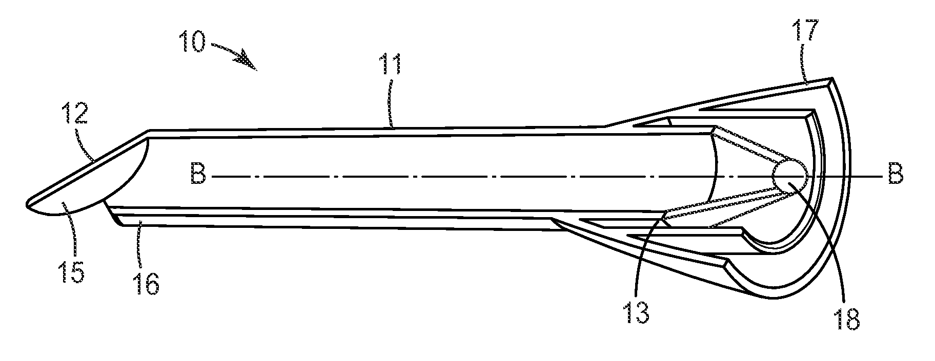
[0012]The invention is advantageous in that it may allow for a relatively simple design of a light guide. Therefore the invention may help minimizing costs of a light device using such a light guide. Further the light guide may be relatively light weight and thus may provide for a relatively convenient handling of the device. The invention may also be advantageous in that it may allow a relatively compact design of the light guide. In particular the light guide because it may extend generally straight which may be advantageous over a curved light guide when used in narrow places, for example in a patient's mouth. The light guide of the invention may further provide for a relatively low thermal conduction. Thus the light guide may be advantageous in that it stays relatively cool at an end opposite of an end receiving light from a light source.
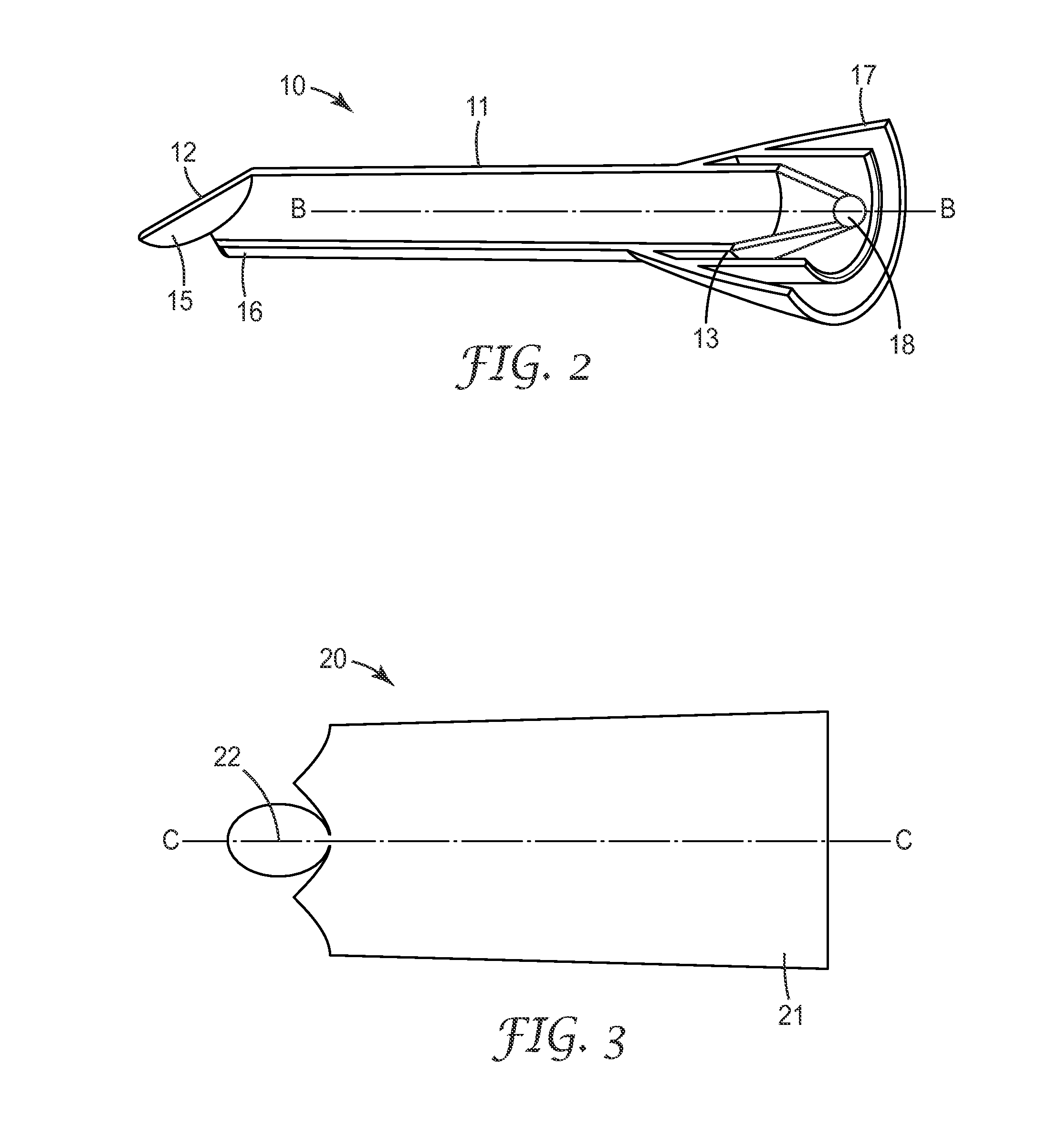
[0046]The invention according to the specified methods may be advantageous for forming a relatively inexpensive light guide. Such a light guide preferably also helps in providing a relatively high convenience in use of a light device in combination with the light guide. This is because the light guide may be relatively light weight so that a manipulation of the device may be facilitated. Further disinfection may be facilitated, or made unnecessary for at least some embodiments of the present invention.

Problems solved by technology

Additionally, a pivotal connection between the housing and the handle permits limited pivotal adjustment of the angle of the housing relative to the handle for improved manipulation and user comfort.

Method used


Image

  • Light guide for a dental light device and a method of making the light guide
  • Light guide for a dental light device and a method of making the light guide
  • Light guide for a dental light device and a method of making the light guide

Examples


Embodiment Construction

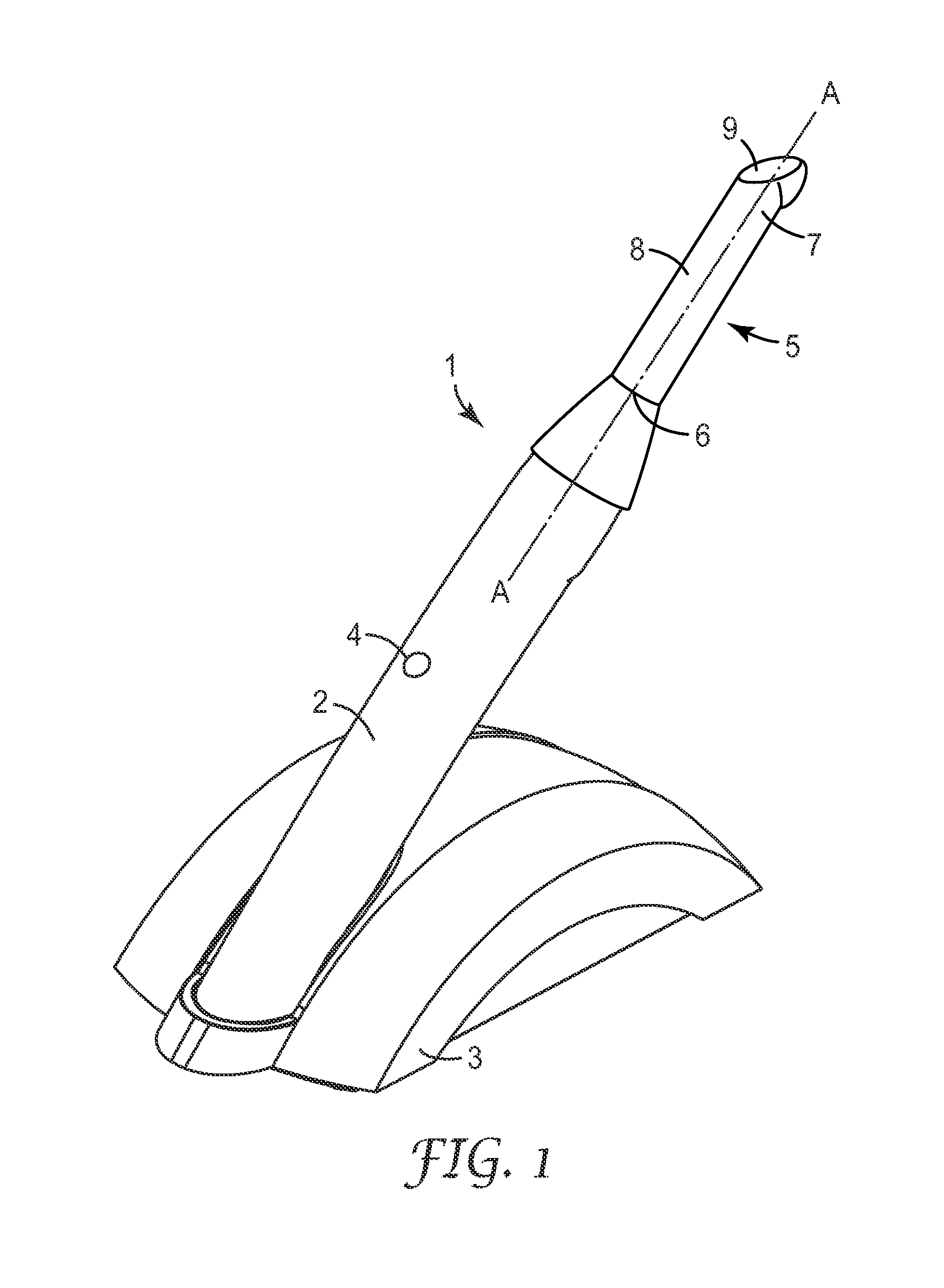
[0056]FIG. 1 shows a dental light device 1 as it may be used in dentistry, for example for providing light to a light hardenable material for initiating the material to harden. The light device 1 comprises a battery powered hand piece 2 and a charger device 3 for recharging the battery of the hand piece 2. The hand piece 2 may be removed from the charger device 3 for use and may then operate generally independently from the charger device 3. In particular there may not be any wired connection between the hand piece 2 and the charger device 3. The hand piece 2 may have a light source (not visible) that can be switched on and / or off by a switch 4. The hand piece 2 further comprises a light guide 5 which is adapted to guide light provided by the light source out of the device, for example toward a dental material. The light guide 5 has a reflector tube 8 with a first end 6 that is oriented toward the light source, and extends generally straight along a longitudinal axis A between the f...


PUM

PropertyMeasurementUnit
Angleaaaaaaaaaa
Angleaaaaaaaaaa
Shapeaaaaaaaaaa

Abstract

A light guide adapted for use with a dental light device has a reflector tube for receiving light from a light source of a light device and for guiding the light toward an end of the reflector tube. The light guide comprises further a reflector plate adjacent the end of the reflector tube. The reflector plate has a reflective face which is arranged inclined relative to the longitudinal axis. The light guide may facilitate handling of a light device in use, and may help minimizing costs.

Description

CROSS-REFERENCE TO RELATED APPLICATIONS[0001]This application claims priority to European Patent Application No. 09180290.0, filed Dec. 22, 2009.FIELD OF THE INVENTION[0002]The invention relates to a dental light guide, and in particular to a light guide having an elongated reflector tube and a reflector plate inclined thereto. The invention further relates to a method of making a light guide for a dental light device.BACKGROUND ART[0003]Light curable materials are widely used in dentistry for the restoration of teeth. Such materials typically can be made to provide optical characteristics that resemble those of natural teeth. Therefore those materials are a favored alternative to less pleasant looking amalgam materials, for example.[0004]Light-hardenable materials often include a polymerizable matrix material and filler materials including colorants, and may initially be generally soft or flowable so that they can be applied in a desired location and shape. For example, for restora...

Claims


Application Information

Patent Timeline
IPC IPC(8): A61N5/06B21D22/20B21D51/02
CPCA61C1/088A61C19/004G02B6/0096G02B6/0008G02B6/0006
Inventor GRAMANN, JENSGUGGENBERGER, RAINERHARRE, MANFREDWELKER, STEFAN K.
Owner 3M INNOVATIVE PROPERTIES CO
Learn More