Ultrasound examination apparatus and ultrasound examination method

an examination apparatus and ultrasound technology, applied in the field of ultrasound examination methods and ultrasound examination apparatuses, can solve the problems of subject discomfort and inability to accurately render the lesion area, and achieve the effect of improving image quality

Active Publication Date: 2012-10-04
PANASONIC CORP
View PDF9 Cites 15 Cited by
  • Summary
  • Abstract
  • Description
  • Claims
  • Application Information

AI Technical Summary

Benefits of technology

[0009]Accordingly, one or more exemplary embodiments of the present disclosure

Problems solved by technology

However, in mammography screening, when imaging of a breast having high tissue density is performed using X-ray, there is a possibility that accurate rendering of a lesion area is not possible, such as when the

Method used


Image

  • Ultrasound examination apparatus and ultrasound examination method
  • Ultrasound examination apparatus and ultrasound examination method
  • Ultrasound examination apparatus and ultrasound examination method

Examples


embodiment 1

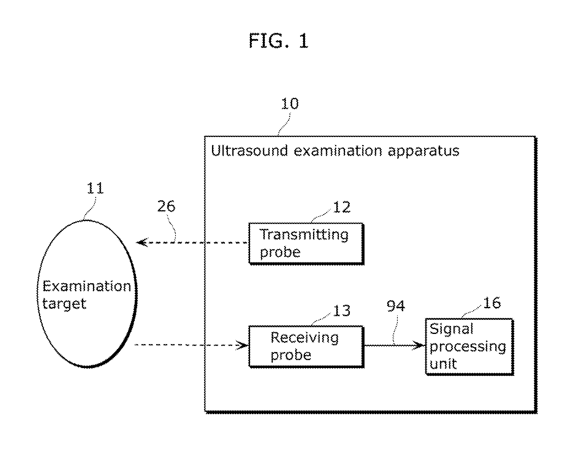
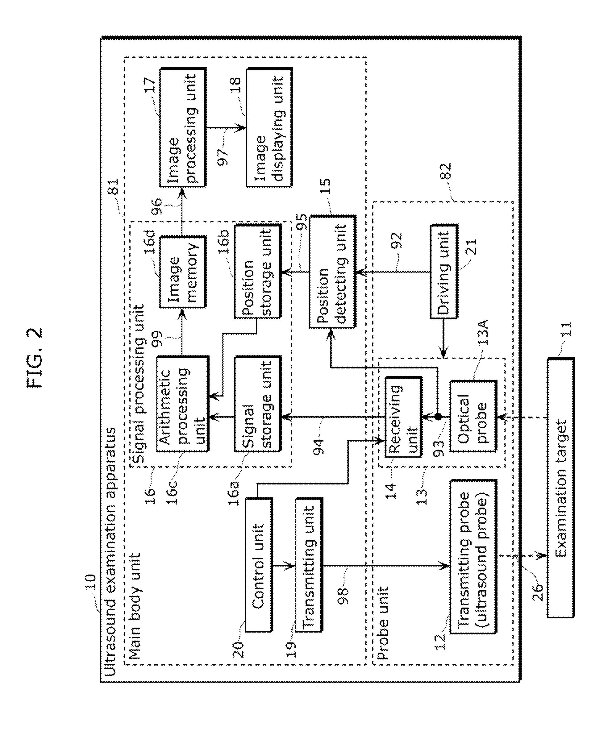
[0066]An ultrasound examination apparatus according to Embodiment 1 of the present disclosure includes a receiving probe which detects reflected ultrasonic waves, without contact with an examination target. In addition, the ultrasound examination apparatus causes the non-contact receiving probe to move, with a transmitting probe in a fixed (stationary) state with respect to the examination target Accordingly, the ultrasound examination apparatus is capable of providing an ultrasound examination apparatus capable of reducing the amount deformation of an examination target during examination and improving image quality.

[0067]First, the basic configuration of the ultrasound examination apparatus according to Embodiment 1 of the present disclosure shall be described.

[0068]FIG. 1 is a block diagram showing the outline configuration of an ultrasound examination apparatus 10 according to Embodiment 1 of the present disclosure.

[0069]The ultrasound examination apparatus 10 is an ultrasound e...

embodiment 2

[0179]In Embodiment 2 of the present disclosure, a projector including an optical probe shall be described.

[0180]FIG. 12A is diagram showing the configuration of a projector 71 according to Embodiment 2 of the present disclosure. FIG. 12B is a diagram for describing the operation of an optical probe 13B included in the projector 71. In this embodiment, a configuration obtained by modifying the optical probe 13A described in Embodiment 1 is used for the purpose of touch detection for a projector. It should be noted that among the constituent elements included in the optical probe 13B included in the projector 71, constituent elements that are the same as those in the optical probe 13A described in Embodiment 1 are given the same reference signs as in Embodiment 1, and description thereof shall not be repeated.

[0181]As shown in FIG. 12A, the projector 71 projects a video onto a display body 72 such as a screen, a wall, or a table. In addition, the projector 71 includes the optical pro...


PUM


Abstract

The ultrasound examination apparatus according to an exemplary embodiment of the present disclosure is an ultrasound examination apparatus for observing an inside of a body of a living subject and includes: a transmitting probe that transmits ultrasonic waves to an inside of an examination target which is a part of the living subject; a receiving probe that detects microscopic displacement on a surface of the examination target without contact with the examination target, to detect reflected ultrasonic waves which are the to ultrasonic waves reflected from the inside of the examination target;
and a signal processing unit that generates an image of the inside of the examination target, based on the reflected ultrasonic waves during a scanning operation in which the transmitting probe is kept fixed with respect to the examination target and the receiving probe is moved with respect to the examination target.

Description

CROSS REFERENCE TO RELATED APPLICATIONS[0001]This is a continuation application of PCT Patent Application No. PCT / JP2011 / 005677 filed on Oct. 11, 2011, designating the United States of America, which is based on and claims priority of Japanese Patent Application No. 2010-236169 filed on Oct. 21, 2010. The entire disclosures of the above-identified applications, including the specifications, drawings and claims are incorporated herein by reference in their entirety.TECHNICAL FIELD[0002]Apparatuses and methods consistent with one or more exemplary embodiments of the present disclosure relate to ultrasound examination apparatuses and ultrasound examination methods for observing an inside of a body of a living subject.BACKGROUND ART[0003]Development is ongoing for various types of techniques for supporting mass health examinations primarily aimed at early discovery of breast cancer. One of these is mammography screening which utilizes a breast imaging technique using X-ray. However, in ...

Claims


Application Information

Patent Timeline
IPC IPC(8): A61B6/00A61B8/12
CPCA61B8/5292A61B8/0825A61B8/0841A61B8/14A61B8/15A61B8/4245A61B5/0059A61B5/0064A61B5/0091A61B8/4218A61B8/4254A61B8/4263
Inventor NAGATA, TAKAYUKIKADOWAKI, SHINICHI
Owner PANASONIC CORP
Why Eureka
Try Eureka