Implantable Catheter and Method of Using Same

a technology of implantable catheters and catheters, which is applied in the direction of multi-lumen catheters, catheters, suction devices, etc., can solve the problems of unattractive one-size-fits-all-purpose lengths for patients, inaccurate placement of the tip, and limited use of these devices

Inactive Publication Date: 2012-10-04
ANGIODYNAMICS INC
View PDF1 Cites 7 Cited by
  • Summary
  • Abstract
  • Description
  • Claims
  • Application Information

AI Technical Summary

Benefits of technology

[0013]The catheter of the present invention comprises a hub member that is selectively connected to a catheter tube and at least one extension leg with a connector at its distal end for attachment to other conventional medical devices. In certain aspects the catheter comprises a hemostasis tapered plug. Alternative aspects of the catheter comprise a locking mechanism and / or attachment tube(s). The catheter of the present invention provides a conduit of user determinative length to be established between attached medical devices and the patient's internal fluid pathways.

Problems solved by technology

A major problem with implanted catheters is accurate placement of the tip of the catheter lumen.
Though there are many methods known in the art whereby a radiopaque tip may be placed on a catheter tube for better visualization during implantation, the use of these devices is limited by the fact that the hub to tip length of the catheter tube is conventionally fixed.
The use of one standard length for every patient is unattractive due to the fact that this typically results in excessive catheter tube being exposed outside the body after implant of the catheter on smaller patients.
The conventional solution of cutting the catheter to the desired length removes the radiopaque tip portion of the catheter tube, which results in a loss of implant accuracy.
Further, the conventional process of determining the proper length for the tunnel (i.e., length from outside the body to the venotomy site) and the proper length catheter for placement in the vein to ensure that the tip is at the desired location is quite crude and imprecise.
A problem with this approach, however, is that it does not always provide the physician with the exact catheter tip placement that is desired.
Some common problems that occur over extended use include weakening or breakage of an implanted catheter's clamps, luer ends, extension tubes, or the catheter body itself.
Currently known in the art are repair systems that repair a broken or damaged implantable catheter but have several limitations.
A number of limitations exist with the currently known repair systems.
This means that if the extension tubing is broken or damaged with less than 4.5 cm of viable tubing left then such a currently known repair kit system cannot be used.
Furthermore, another limitation of currently known repair systems is a lack in durability and strength.
This means current repair systems often do not have a fluid-tight fit and tend to leak, and are also made materials that have the likelihood to wear and break over time.

Method used


Image

  • Implantable Catheter and Method of Using Same
  • Implantable Catheter and Method of Using Same
  • Implantable Catheter and Method of Using Same

Examples


first embodiment

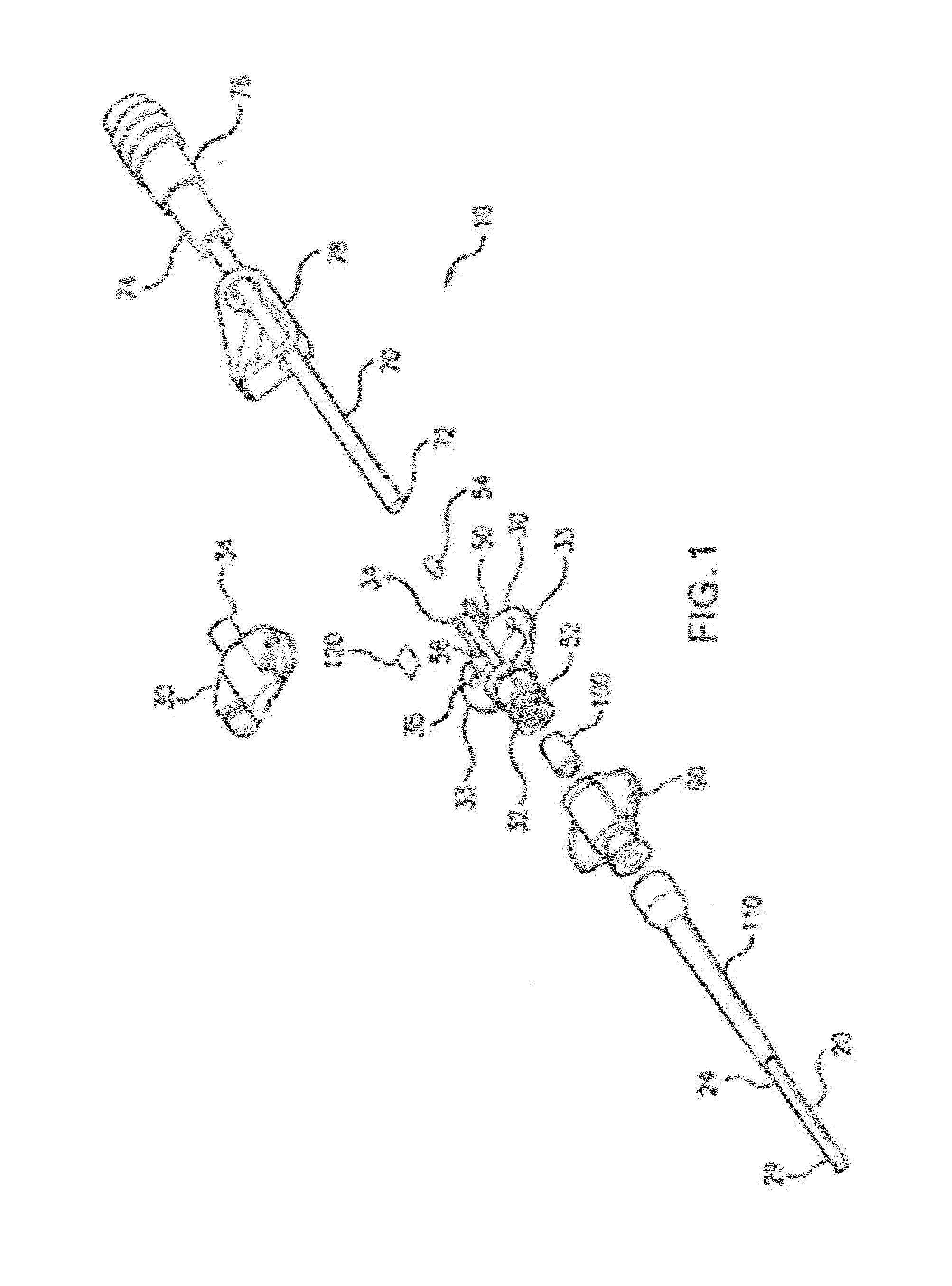
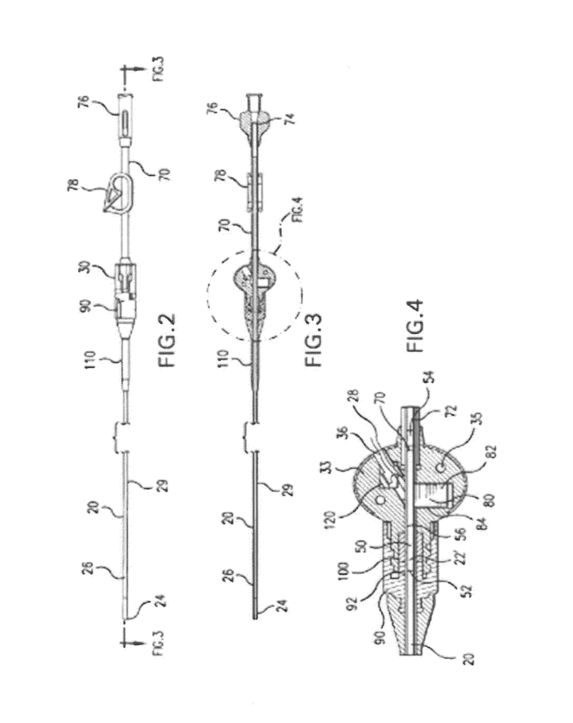
[0059]Referring to FIGS. 1-5, an implantable catheter of the present invention is illustrated. As shown in FIG. 1, the catheter 10 comprises a single-lumen catheter tube 20, a means for trimming the catheter tube, a hub member 30, and an attachment tube 50. The catheter tube 20 has a distal end 22 and a tip 24. In one aspect, at least a portion of the catheter tube comprises a radiopaque material that is formed thereon the catheter tube through means currently known in the art. In one exemplary aspect, a stripe of radiopaque material is formed on the catheter tube proximate the tip 24 of the catheter tube 20. In another exemplary aspect, at least a portion of the tip of the catheter tube is formed of the radiopaque material. One would appreciate that it is contemplated that the radiopaque material can be formed in any desired geometric shape on any portion of the catheter tube proximate to or at the tip of the catheter tube.

[0060]The hub member 30 comprises a proximal port 32 and a ...

second embodiment

[0078]FIGS. 6-8 illustrate the catheter 10 of the present invention. In this aspect, the attachment tube 50 of the catheter assembly has a first end portion 52 that has a barbed exterior surface portion forming a barbed connector 58, an intermediate portion 60 that has a raised shoulder member 62, and a second end portion 54 adapted to connect to an extension tube 70. Here, the end of the single lumen catheter tube 20 is connected to the first end portion 52 of the attachment tube after being trimmed to a desired length via cutting means known in the art. As one will appreciate, the barbed connector 58 at the first end portion of the attachment tube provides for internal sealing between the attachment tube 50 and the single lumen catheter 20. The attachment tube, with the trimmed end of the catheter tube mounted thereon, is then drawn up a conduit 40 defined within a portion of the hub member 30 until the raised shoulder member 62 of the attachment tube is positioned into a locking ...

third embodiment

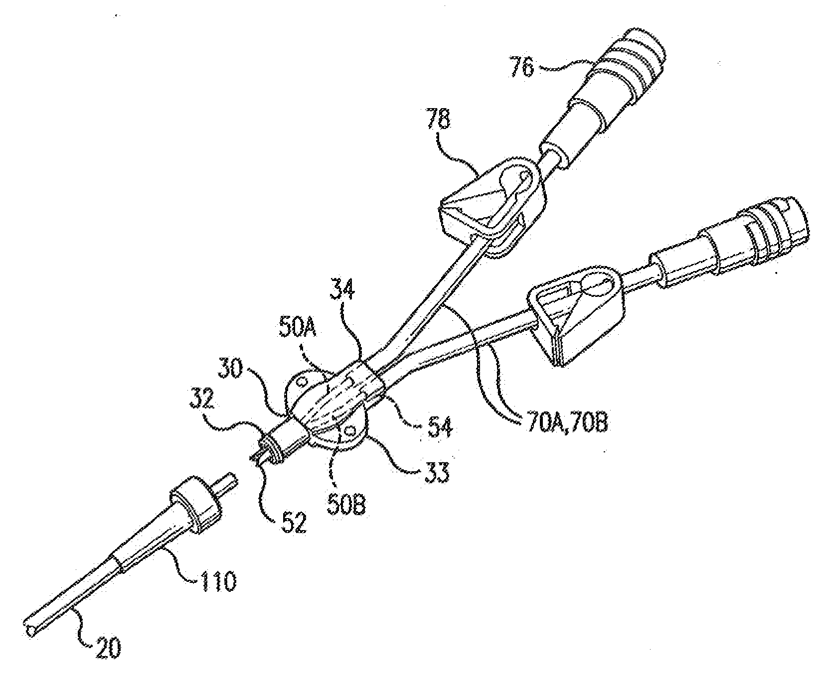
[0080]Referring now to FIGS. 9-11, a dual lumen catheter of the present invention is illustrated. In this aspect, the dual lumen catheter tube 20 is connected to respective attachment tubes 50A, 50B of a pair of attachment tubes after trimming to the desired length. The pair of attachment tubes are mounted at least partially therein the hub member 30 of the catheter. In one aspect, the first ends 52 of the attachment tubes have a D-shaped cross-section and are positioned in opposition. In another aspect, portions of the first ends 52 of the attachment tubes have peripherally extending barb portions 58. In one aspect, the barbed portions of the pair of attachment tubes are shaped and positioned to form staggered double barbed portions. As one would appreciate, the extension legs are positioned in fluid communication with the attachment tubes.

[0081]In this aspect, the catheter 10 comprises a hemostasis taper sleeve 110 that is axially and slideably mounted thereon a portion of the dua...


PUM

PropertyMeasurementUnit
lengthaaaaaaaaaa
inner diameteraaaaaaaaaa

Abstract

A catheter for implantation into a patient having a catheter tube having a distal end, a means for trimming the distal end of the catheter tube after subcutaneous insertion of the tip of the catheter lumen into a desired position within the patient to form a trimmed end portion, and a means for selectively positioning each respective lumen of the trimmed end portion of the catheter tube into fluid communication with the respective first end of one attachment tube. The attachment tube is select fluid communication with a desired medical device. Additionally, a repair kit and method of repairing a damaged catheter in which a fluid-tight connection is created between an existing implanted catheter and a replacement tubing.

Description

CROSS-REFERENCE TO RELATED APPLICATIONS[0001]This application is a continuation-in-part application of U.S. application Ser. No. 12 / 643,562, filed on Dec. 21, 2009, which is a Divisional of application Ser. No. 11 / 392,257, filed on Mar. 29, 2006, now U.S. Pat. No. 7,740,616, which claims the benefit of U.S. Provisional Application No. 60 / 666,337, filed on Mar. 29, 2005, which are herein incorporated by reference in their entireties.FIELD OF THE INVENTION[0002]The invention relates in general to implantable medical devices. More particularly, the invention relates to implantable catheters, and methods of using same, that allow the catheter tube to be sized to a desired length while also allowing for the accurate placement of the tip of the catheter tube within a subject.BACKGROUND OF THE INVENTION[0003]The use of implantable catheters in the art of drug delivery and blood sampling is well known, in which at least one of several known types of catheters is implanted in a patient's sys...

Claims


Application Information

Patent Timeline
Patent Type & Authority Applications(United States)
IPC IPC(8): A61M25/00B23P6/00
CPCA61M25/0017A61M25/0097A61M25/0026A61M25/01Y10T29/49718A61M1/3659A61M1/3661
Inventor NENTWICK, BRIAN F.KENNY, JAMES STEVEN
Owner ANGIODYNAMICS INC
Why Eureka
Try Eureka