Fracturing calcifications in heart valves

a heart valve and calcification technology, applied in the field of heart valve calcification fracturing devices and methods, can solve problems such as impede the proper movement of valve leaflets, and achieve the effect of increasing leaflet pliability and mobility

Active Publication Date: 2012-10-04
PI CARDIA
View PDF7 Cites 49 Cited by
  • Summary
  • Abstract
  • Description
  • Claims
  • Application Information

AI Technical Summary

Benefits of technology

[0005]The present invention seeks to provide improved devices and methods that may be used for fracturing calcifications in aortic valve leaflets, in order to incr

Problems solved by technology

This involves calcium buildup in the valve

Method used


Image

  • Fracturing calcifications in heart valves
  • Fracturing calcifications in heart valves
  • Fracturing calcifications in heart valves

Examples


Embodiment Construction

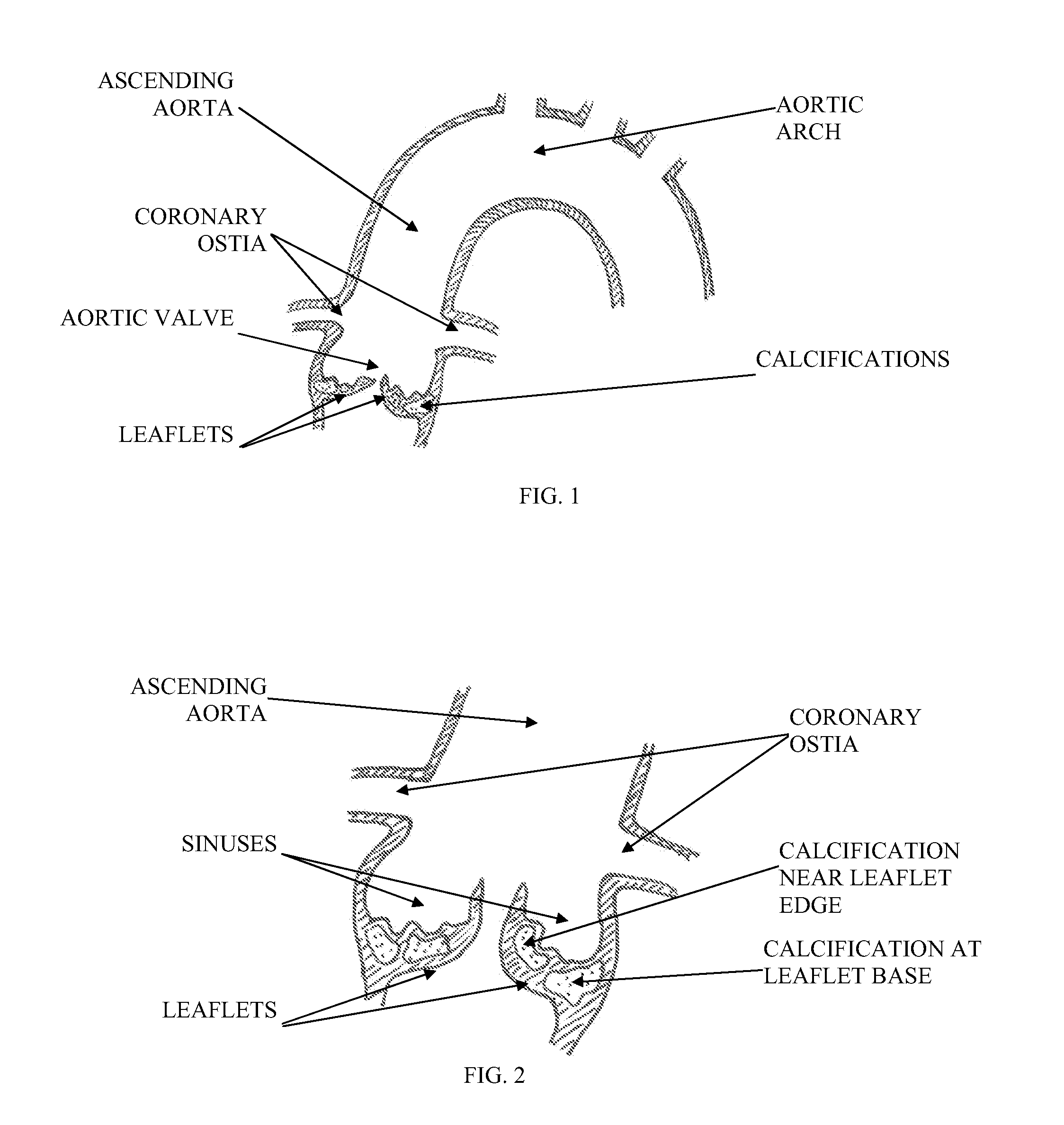
[0032]Reference is now made to FIG. 1, which illustrates the anatomy of a calcified aortic valve, ascending aorta and aortic arch. Calcifications may be embedded in the valve leaflets, which are connected to the aortic wall just below the coronary ostia.

[0033]Reference is now made to FIG. 2, which is an enlarged view of a calcified aortic valve. The leaflets create concave sinuses on their aortic aspect, just below the coronary ostia. Calcification can be embedded in the leaflets, making the leaflets thicker and less pliable. Specifically, calcification that occurs at the leaflet base, i.e., where the leaflet connects to the annulus or aortic wall, can significantly impair the mobility of the leaflet, similar to friction in a door-hinge.

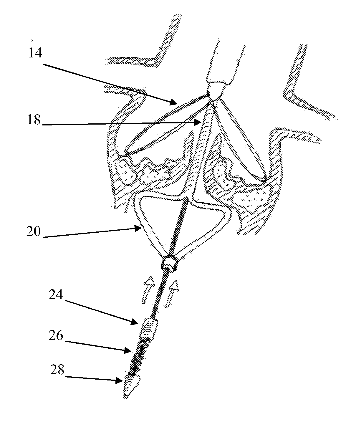
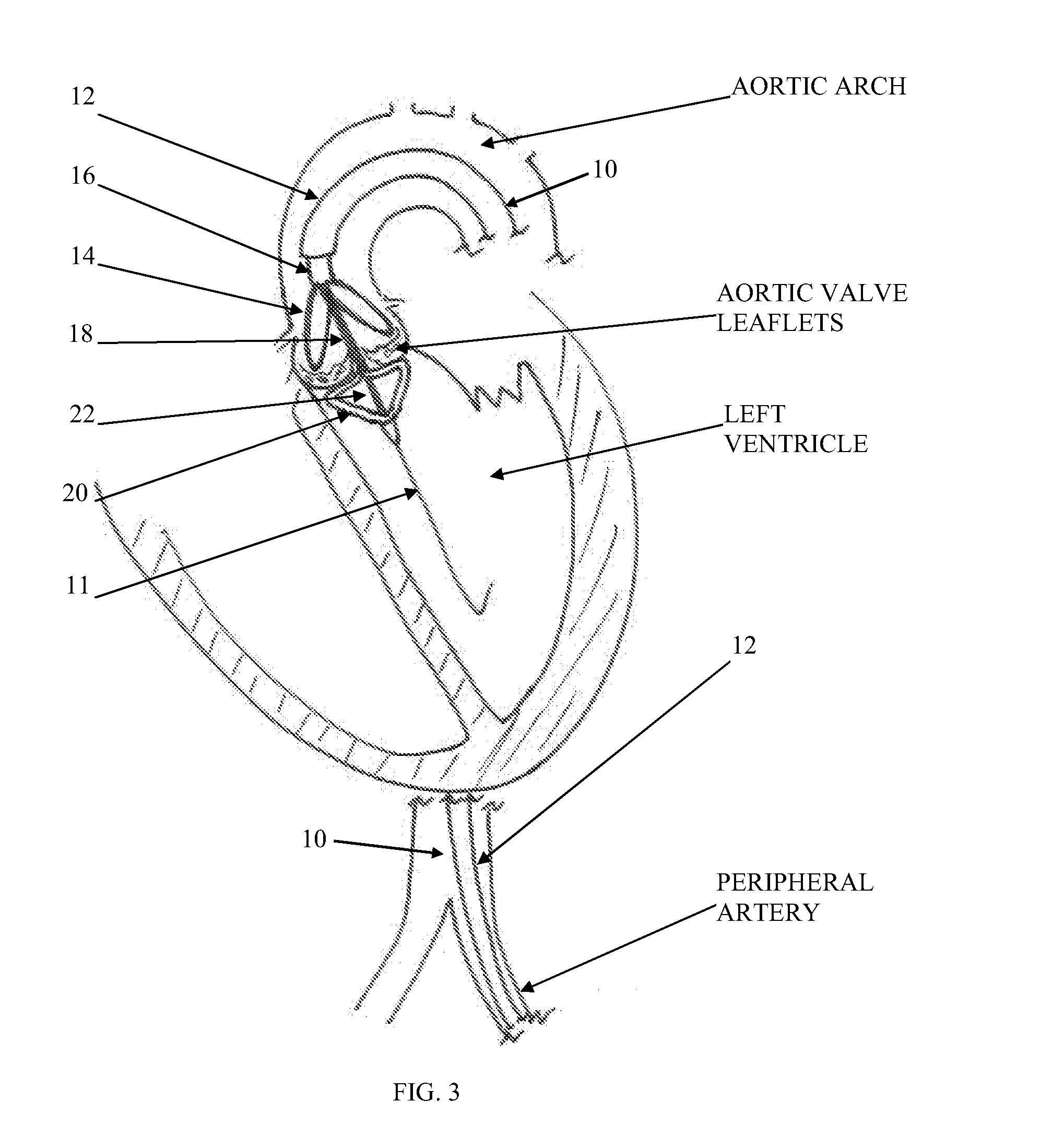
[0034]Reference is now made to FIG. 3, which illustrates a distal part of an impactor catheter system that can be used for fracturing aortic valve calcifications, constructed and operative in accordance with a non-limiting embodiment of the invention...


PUM


Abstract

A device for fracturing calcifications in heart valves including an expandable stabilizer (14) and expandable impactor arms (20) assembled on and deployed by a delivery system (10), wherein the delivery system (10) is operable to move the impactor arms (20), while in an expanded position, with respect to the stabilizer (14) with sufficient energy so as to fracture a calcification located in tissure which is sandwiched between the stabilizer (14) and the impactor arms (20).

Description

FIELD OF THE INVENTION[0001]The present invention generally relates to devices and methods for fracturing calcifications in heart valves, such as aortic valve leaflets.BACKGROUND OF THE INVENTION[0002]Essential to normal heart function are four heart valves, which allow blood to pass through the four chambers of the heart in the proper flow directions. The valves have either two or three cusps, flaps, or leaflets, which comprise fibrous tissue that attaches to the walls of the heart. The cusps open when the blood flow is flowing correctly and then close to form a tight seal to prevent backflow.[0003]The four chambers are known as the right and left atria (upper chambers) and right and left ventricles (lower chambers). The four valves that control blood flow are known as the tricuspid, mitral, pulmonary, and aortic valves. In a normally functioning heart, the tricuspid valve allows one-way flow of deoxygenated blood from the right upper chamber (right atrium) to the right lower chamb...

Claims


Application Information

Patent Timeline
IPC IPC(8): A61B17/22
CPCA61B17/22A61B17/22031A61B2019/464A61B2017/22098A61B17/221A61B2090/064A61B17/22012A61B2017/00544A61B2017/22069
Inventor GOLAN, EREZ
Owner PI CARDIA
Why Eureka
Try Eureka